Switching regulator, DC/DC converter, and LSI system with switching regulator

A switching regulator and switch disconnection technology, which is applied in the direction of converting DC power input to DC power output, control/regulation systems, instruments, etc. The time required for initialization becomes longer and other problems, to achieve the effect of suppressing the inrush current and suppressing the excess current

Inactive Publication Date: 2005-04-20
SOCIONEXT INC
View PDF2 Cites 2 Cited by
  • Summary
  • Abstract
  • Description
  • Claims
  • Application Information

AI Technical Summary

Problems solved by technology

[0008] First, if Figure 11 As shown, there is a problem that the power conversion efficiency decreases in the structure using the inrush current suppression circuit
That is, in Figure 11 In the structure, since the resistance element 51 used to detect the inrush current is inserted in the current path from the power supply, the power loss is on the resistance element 51, and that part of the power consumption reduces the power conversion efficiency of the switching regulator.
[0009] Furthermore, if Figure 12 and Figure 14 As shown, in the structure using a sawtooth wave for the initial operation, although the inrush current generated during the initial operation can be suppressed, the excess current generated during the stable operation cannot be detected and suppressed.
In addition, there is another problem that the time required for initialization becomes longer

Method used


Image

  • Switching regulator, DC/DC converter, and LSI system with switching regulator
  • Switching regulator, DC/DC converter, and LSI system with switching regulator
  • Switching regulator, DC/DC converter, and LSI system with switching regulator

Examples


Embodiment Construction

[0037] Hereinafter, an embodiment of the present invention will be described with reference to the drawings.

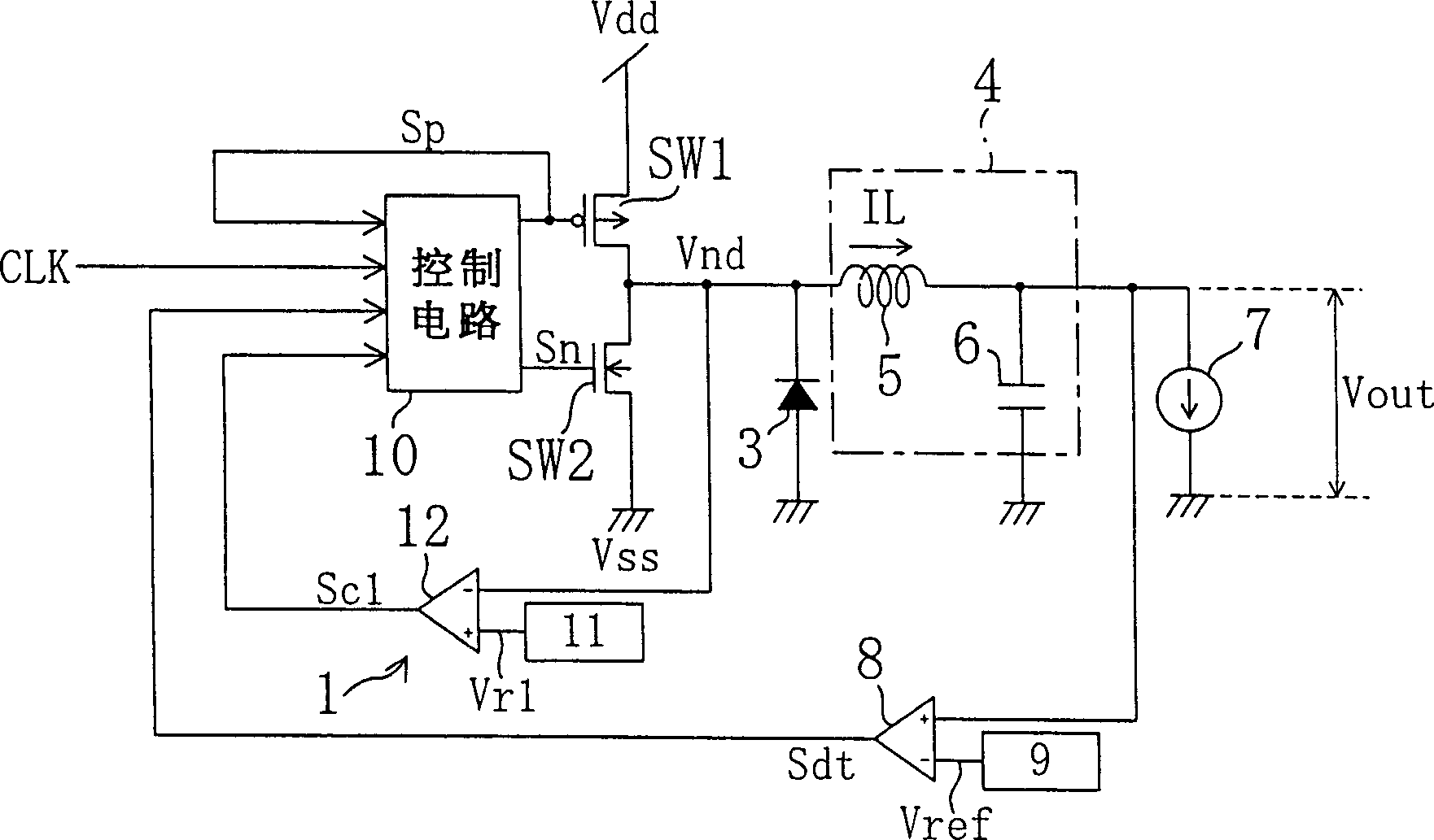
[0038] figure 1 It is a circuit diagram showing the configuration of a switching regulator according to an embodiment of the present invention. figure 1 Among them, SW1 is a first switch made up of p-type MOS transistors, SW2 is a second switch made up of n-type MOS transistors, and the first and second switches SW1 and SW2 are the first switches that can supply the first potential, that is, the power supply potential Vdd. A power supply (hereinafter referred to as "power supply Vdd") and a second power supply (hereinafter referred to as "power supply Vss") capable of supplying a ground potential Vss as a second potential are connected in series. 3 is a diode for allowing current to flow from the power supply Vss when both the first and second switches SW1 and SW2 are off. 4 is a smoothing circuit for smoothing the potential Vnd of the output node between the firs...


PUM


Abstract

A synchronous rectification switching regulator comprising: first and second switches (SW1, SW2) connected in series between a power supply (Vdd) and a ground (Vss); switching the switches (SW1, SW2) on and off A switching control unit (1) for controlling; a smoothing circuit (4) for smoothing an output node potential (Vnd). During the conduction period of the first switch (SW1), if the signal (Sc1) indicates that the output node potential (Vnd) is lower than the first reference potential (Vr1) which is the benchmark for inrush current detection, the control circuit (10) will switch the first switch to (SW1) is disconnected. In other words, in the present invention, the inrush current is detected by using the voltage drop caused by the on-resistance of the first switch ( SW1 ), so no resistance element for detecting the inrush current is required.

Description

technical field [0001] The present invention belongs to a switching regulator used to detect and suppress the inrush current generated when the power is turned on, that is, the so-called initial operation, or such as a short-circuit fault in the output voltage smoothing capacitor. technology of excess current. Background technique [0002] Generally speaking, in a switching regulator used to convert a DC power supply voltage into another DC voltage, how to suppress the generation of inrush current and excess current is a big issue. Here, the inrush current is a current that inrushes to charge the output voltage smoothing capacitor when a switch connected to the power supply is turned on during an initial operation such as when the power supply is turned on. The excess current is an excess current that flows from the power source to the load when a switch connected to the power source is turned on, for example, when a short-circuit fault occurs in the output voltage smoothin...

Claims


Application Information

Patent Timeline
Patent Type & Authority Patents(China)
IPC IPC(8): H02M3/155H02M1/36H02M3/158
CPCH02M1/32H02M1/36H02M3/1588Y02B70/10H02M1/0009H02M3/155
Inventor 梶原准崎山史朗木下雅善里见胜治大谷一弘
Owner SOCIONEXT INC
Why Eureka
Try Eureka