Electronic device and control method thereof

The technology of an electronic device and control method is applied in the direction of machine execution devices, multi-programming devices, cooperative operation devices, etc., and can solve the problems of functional units that cannot work and waste power consumption, etc.

Active Publication Date: 2006-12-13
PANASONIC CORP
View PDF0 Cites 2 Cited by
  • Summary
  • Abstract
  • Description
  • Claims
  • Application Information

AI Technical Summary

Problems solved by technology

[0024] However, the specified time for judging as a timeout is longer than the normal communication time
According to the previous method, in the case that one or more functional units cannot work, it takes a long time before the master device knows whether all the functional units can work
Or the response is not returned, it may be caused by other reasons besides the failure of the functional unit to work
In previous electronic devices, it is difficult for the main device to correctly know whether each functional unit is working
In conventional electronic devices, all functional units are activated, but there are also functional units that are not used by the user, and activation of even functional units that are not used is a major cause of wasteful power consumption.

Method used


Image

  • Electronic device and control method thereof
  • Electronic device and control method thereof
  • Electronic device and control method thereof

Examples


Embodiment 1

[0085] refer to Figure 1 to Figure 7 , the electronic device and its control method according to Embodiment 1 of the present invention will be described.

[0086] First, refer to figure 1 , figure 2 , the structure of the electronic device according to Embodiment 1 of the present invention will be described.

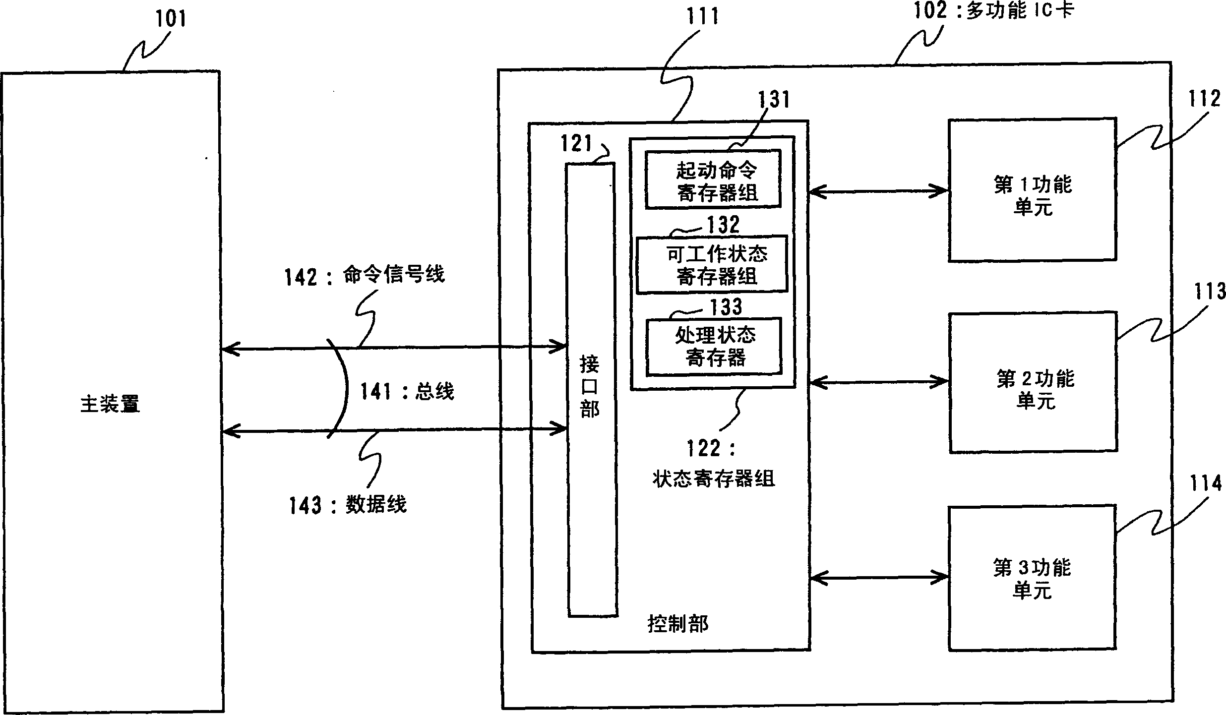
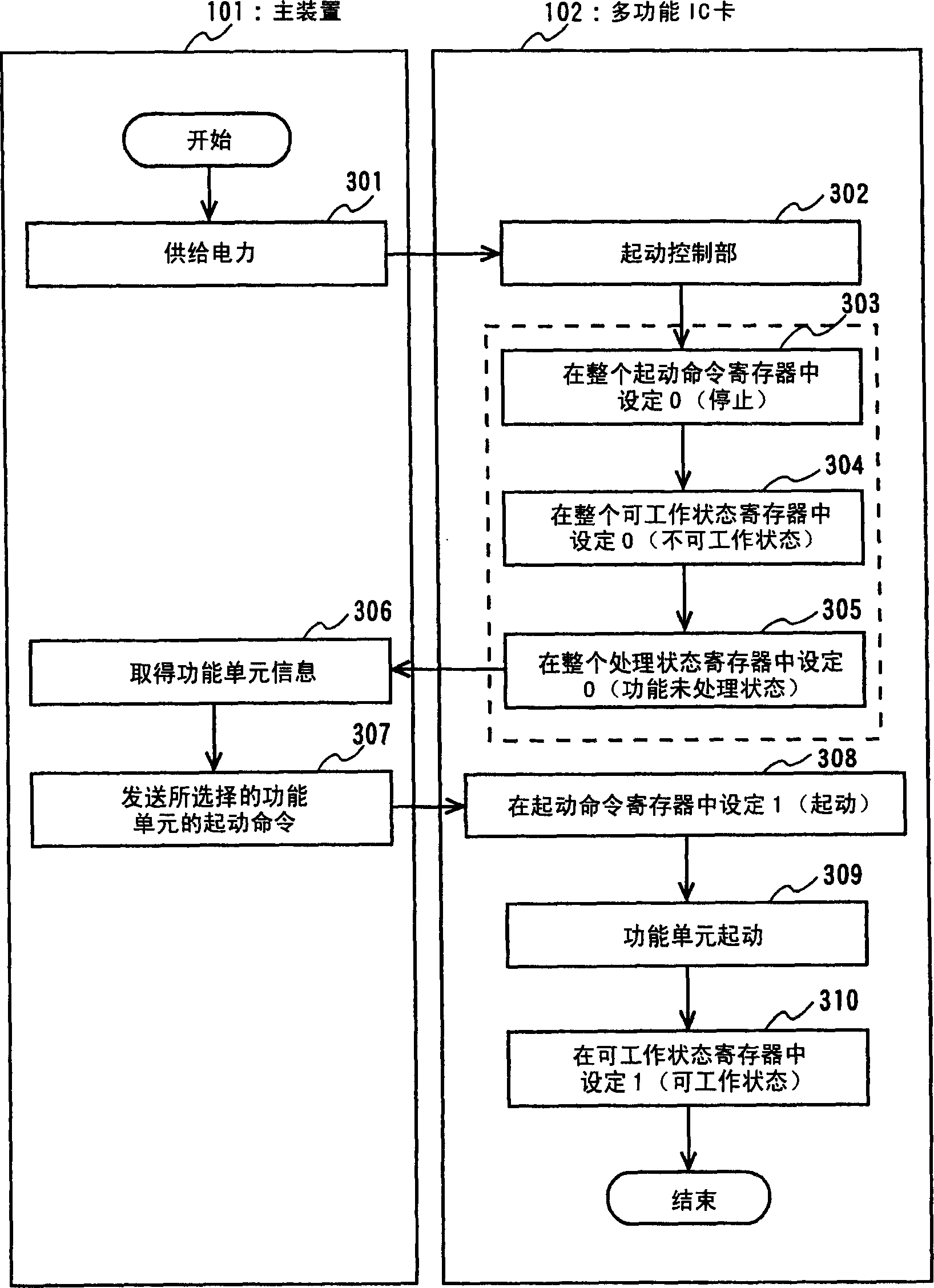
[0087] figure 1 It is a block diagram showing the configurations of the host device 101 and the multi-function IC card 102 according to the first embodiment of the present invention. The main device 101 of Embodiment 1 of the present invention is different from the main device 101 of the prior art ( Figure 15 )same. The multifunctional IC card 102 of Embodiment 1 of the present invention has the multifunctional IC card 1502 ( Figure 15 ) similar structure.

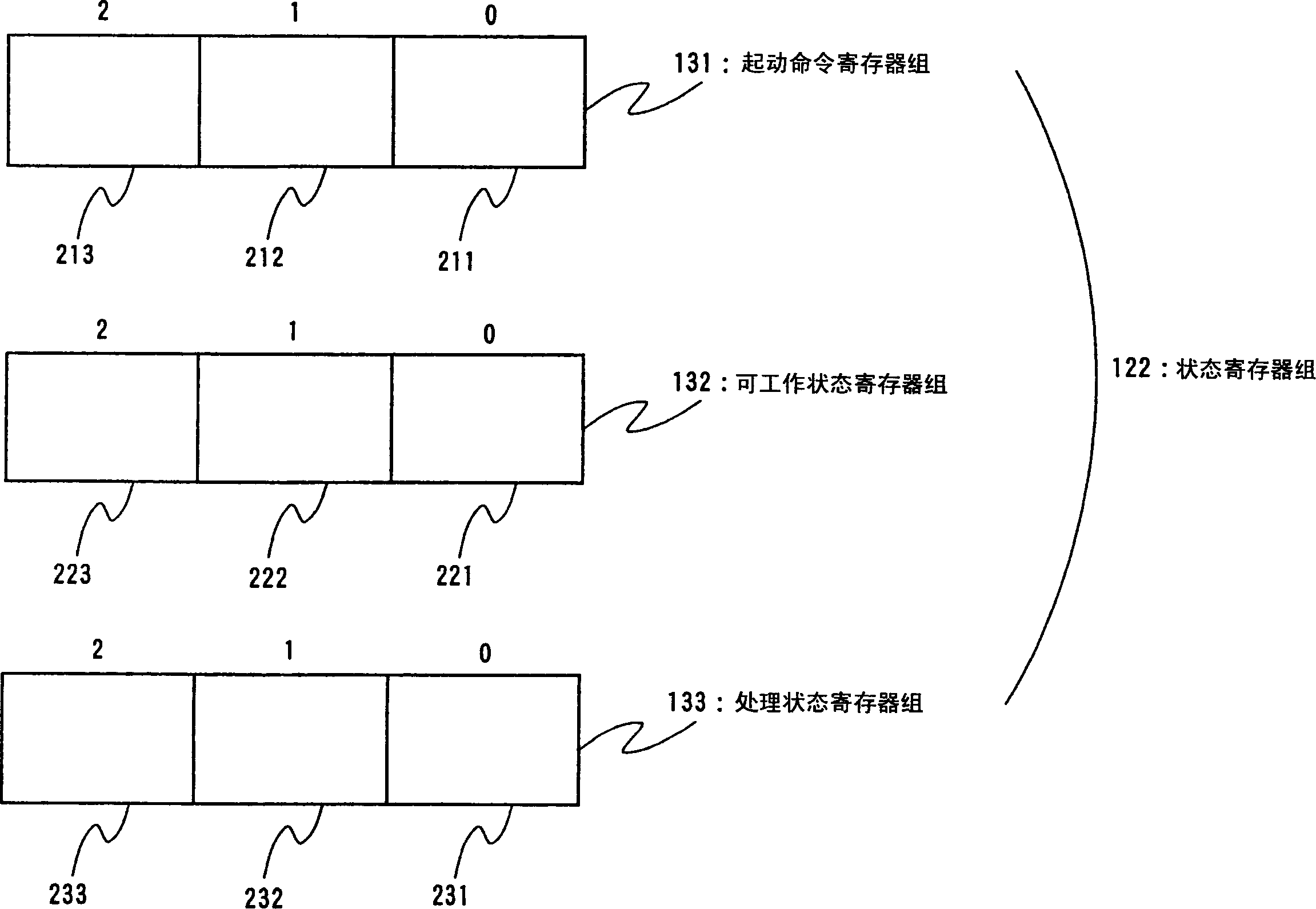
[0088] The multifunctional IC card 102 has a control unit 111 instead of the prior art ( Figure 15 ) of the control unit 1511. The control unit 111 has an interface unit 121 and a status register group 1...

Embodiment 2

[0125] refer to Figure 8 ~ Figure 13 An electronic device and a control method thereof according to Embodiment 2 of the present invention will be described.

[0126] First, refer to Figure 8 , Figure 9 The configuration of an electronic device according to Embodiment 2 of the present invention will be described. Figure 8 It is a block diagram showing the configurations of the host device 101 and the multi-function IC card 802 according to the second embodiment of the present invention. The main device 101 of the second embodiment and the main device 101 of the first embodiment ( figure 1 )same. The multifunctional IC card 802 of embodiment 2 of the present invention has the same as the multifunctional IC card 102 of embodiment 1 ( figure 1 ) similar structure.

[0127] Multifunctional IC card 802, instead of embodiment 1 ( figure 1) of the control unit 111 and has a control unit 811 . The control unit 811 has an interface unit 121 and a status register group 822...

Embodiment 3

[0157] refer to Figure 8 , Figure 14 The electronic device and its control method according to Embodiment 3 of the present invention will be described.

[0158] First, refer to Figure 8 The configuration of an electronic device according to Embodiment 3 of the present invention will be described. Figure 8 It is a block diagram showing the structure of the multifunctional IC card according to the third embodiment of the present invention. The multifunctional IC card of embodiment 3 of the present invention has the same structure as embodiment 2 ( Figure 8 ). Its description is omitted.

[0159] Next, refer to Figure 14 A method of controlling an electronic device according to Embodiment 3 of the present invention will be described. Figure 14 It is a flow chart of the method for restarting the multi-function IC card in embodiment 3 of the present invention when it crashes.

[0160] A case will be described in which the first functional unit (memory module) 112 sta...


PUM


Abstract

An electronic device includes: a control unit having an interface unit for performing communication with an external host device and a state register group; and a plurality of function units for performing communication with the host device via the interface unit. The state register group has a plurality of state registers which are correlated to the function units, respectively, and indicate whether the corresponding function unit is operable and whether the corresponding unit is performing processing. When the control unit receives an instruction from the host device, the control unit transfers the instruction to a function unit if the instruction is for any of the function units, and transmits a state of the state register group as a response to the host device if the instruction is a read instruction of the state register group.

Description

technical field [0001] The invention relates to an electronic device and a control method thereof. Background technique [0002] In recent years, IC cards with storage media such as flash memory (flash memory) have attracted attention as storage devices for portable information devices (eg, portable personal computers, digital cameras, PDAs) that process large amounts of data such as music or video data. And recently, the IC card not only plays the role of a bridge / medium (bridge media) as a memory for data accumulation and data exchange between machines, but also plays a role of a so-called function expansion device of the machine (for example, refer to Non-Patent Document 1). Therefore, an IC card with multiple functional units is called a multi-function IC card. [0003] First, refer to Figure 15 The structure of the prior art multifunctional IC card disclosed in the publication is explained. Figure 15 It is a block diagram showing the structure of a conventional mult...

Claims


Application Information

Patent Timeline
Patent Type & Authority Applications(China)
IPC IPC(8): G06K19/00G06K17/00G06F9/50G06F9/38G06K7/00G06K19/077
CPCG06K19/07733G06K19/077G06K19/0719G06K7/10297G06K7/0008
Inventor 岩田和也足立达也中村清治
Owner PANASONIC CORP
Why Eureka
Try Eureka