Jig for installation inspection
A technology of fixture and installation position, which is applied in the field of fixtures for installation and inspection, and can solve problems such as terminal deformation and fixture cost increase
- Summary
- Abstract
- Description
- Claims
- Application Information
AI Technical Summary
Problems solved by technology
Method used
Image

Examples
no. 1 example
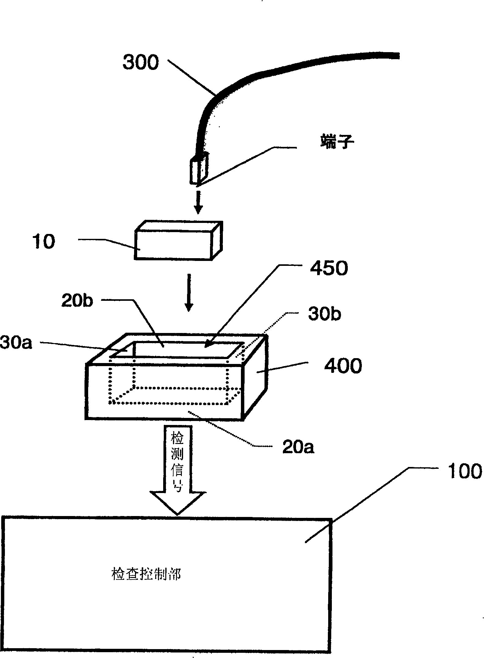
[0027] First refer to figure 1 The principle of checking the mounting state of terminals to which the device for confirming the mounting state of terminals of the present invention is applied will be described. figure 1 It is a schematic diagram for explaining the basic principle of the terminal mounting state confirmation device for detecting the mounting state of the crimping electric wire terminal to the connector according to the first embodiment of the present invention.
[0028] exist figure 1 Among them, 10 is a connector shell (hereinafter referred to as "connector") constituting the end of the wire bundle to be inspected. At a predetermined position in the connector 10, one end of a predetermined specification cut and crimped wire 300 is Insert the terminal to the specified depth.
[0029] The cut and crimped electric wire 300 attached to this connector is cut to a predetermined length in advance, and a terminal of a predetermined specification to be attached to the...
no. 2 example
[0110]In the above description, an example in which a storage space for accommodating a connector is provided approximately in the center of the accessory part has been described. However, the present invention is not limited to the above examples. For example, one accessory part may have two or more accommodation spaces for accommodating two or more connectors. Alternatively, two or more accessory parts may be accommodated in the connector housing part of the connector holding part, and a connector may be accommodated in each accessory part. With the above configuration, it is possible to check the state where the terminals are inserted into two or more connectors.
[0111] A second embodiment of the present invention in which a plurality of connectors are accommodated in the connector accommodating portion of the connector holding portion will be described with reference to FIG. 6 . Fig. 6 is a diagram for explaining accessory parts of a second embodiment of the present inv...
no. 3 example
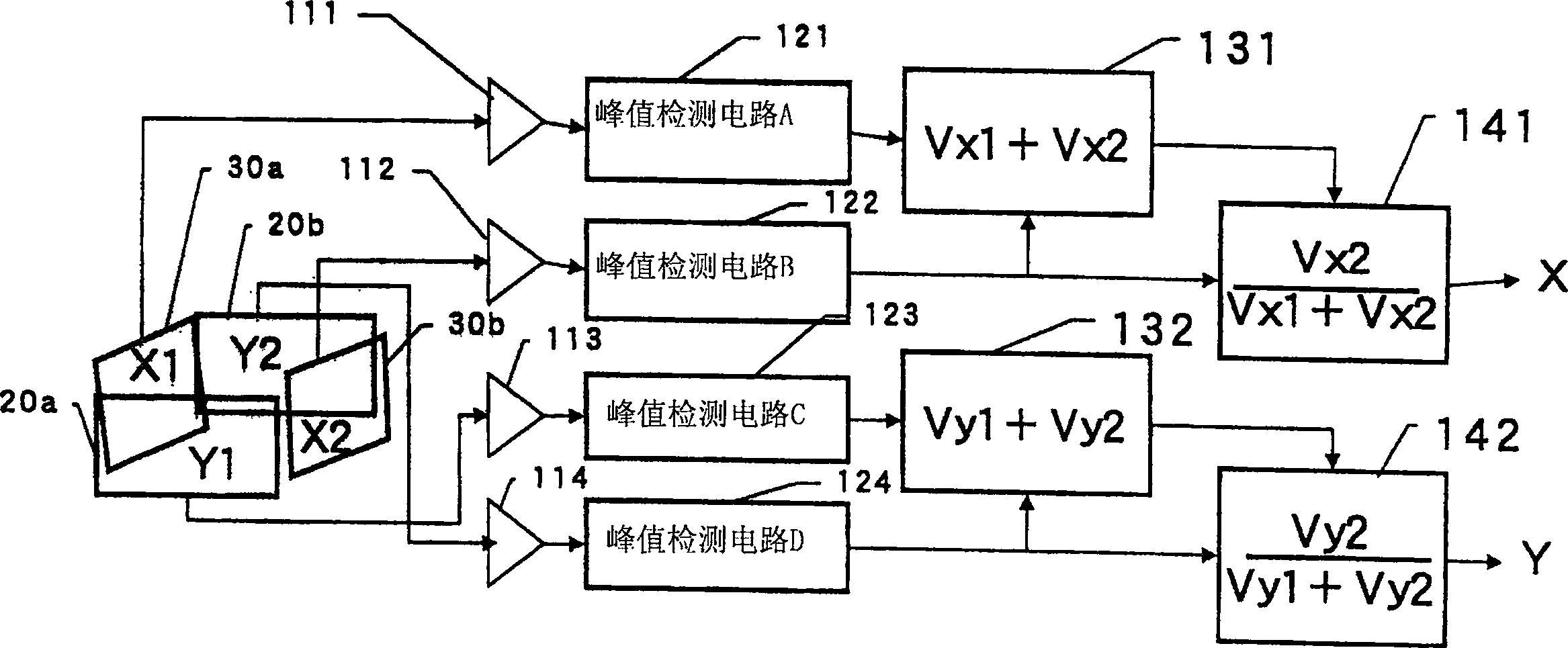
[0119] In addition, in the embodiments described above, an example in which the X-axis or Y-axis sensor boards are arranged opposite to each other with the connector housings interposed therebetween has been described. However, the present invention is not limited to the above example, and the two sensor boards may be positioned on one side of the connector housing portion with a certain distance apart and approached approximately in parallel.
[0120] For example, by attaching sensor boards to both sides of a thin-plate-shaped insulating material and placing them on the inner wall surface of one side of the connector housing, the two sensor boards are separated by a certain distance on one side of the connector housing. It is sufficient to position and set approximately parallel.
[0121] In addition, the arrangement method of the sensor board is not limited to the above example, and may be embedded in the side wall, or attached to the side wall of the attachment part when us...
PUM
 Abstract
Description
Claims
Application Information
 - R&D Engineer
- R&D Manager
- IP Professional
- Industry Leading Data Capabilities
- Powerful AI technology
- Patent DNA Extraction
Browse by: Latest US Patents, China's latest patents, Technical Efficacy Thesaurus, Application Domain, Technology Topic.
© 2024 PatSnap. All rights reserved.Legal|Privacy policy|Modern Slavery Act Transparency Statement|Sitemap