Recessed lignting fixture

A technology of embedded lamps and lampshades, which is applied in lighting and heating equipment, slender light sources, light source combinations, etc., can solve problems such as attenuation, and achieve the effects of avoiding facial shadows, good lighting environment, and good room atmosphere

Inactive Publication Date: 2007-01-17
哈特姆特 S 英格尔
View PDF0 Cites 5 Cited by
  • Summary
  • Abstract
  • Description
  • Claims
  • Application Information

AI Technical Summary

Problems solved by technology

However, this portion of direct light or light entering the area is partially or completely attenuated, which again becomes a disadvantage

Method used


Image

  • Recessed lignting fixture
  • Recessed lignting fixture
  • Recessed lignting fixture

Examples


Embodiment Construction

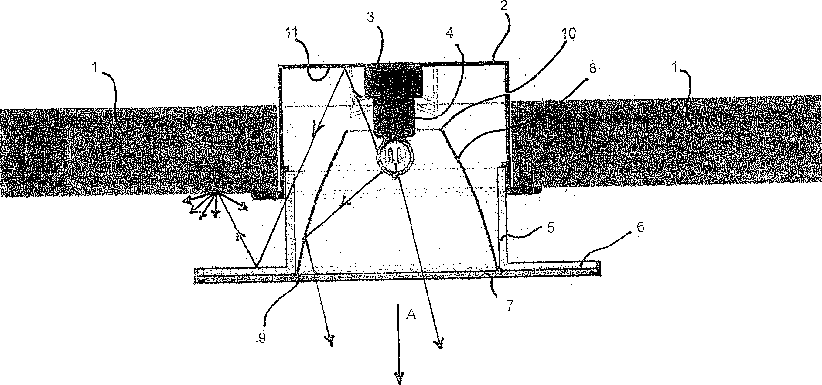
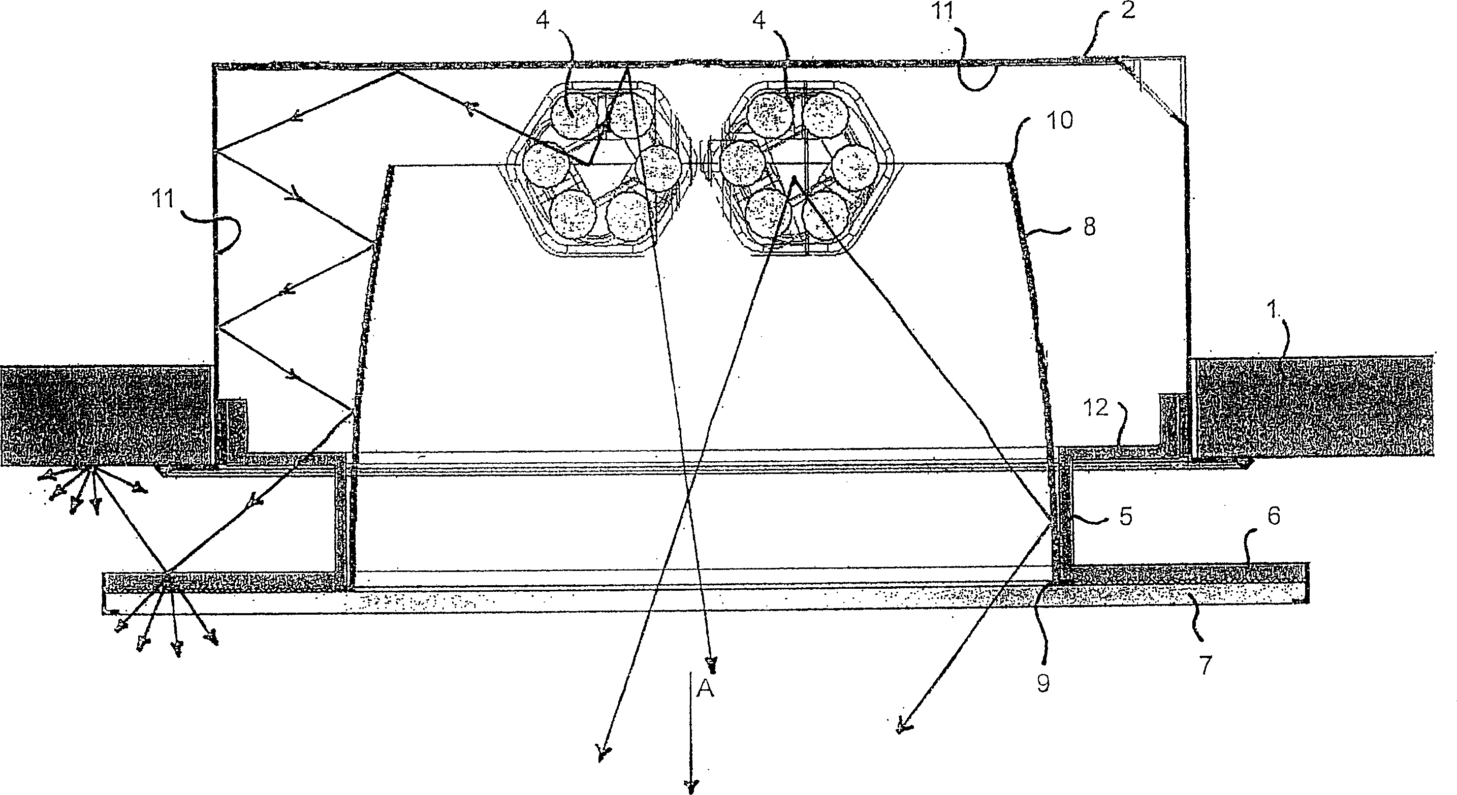
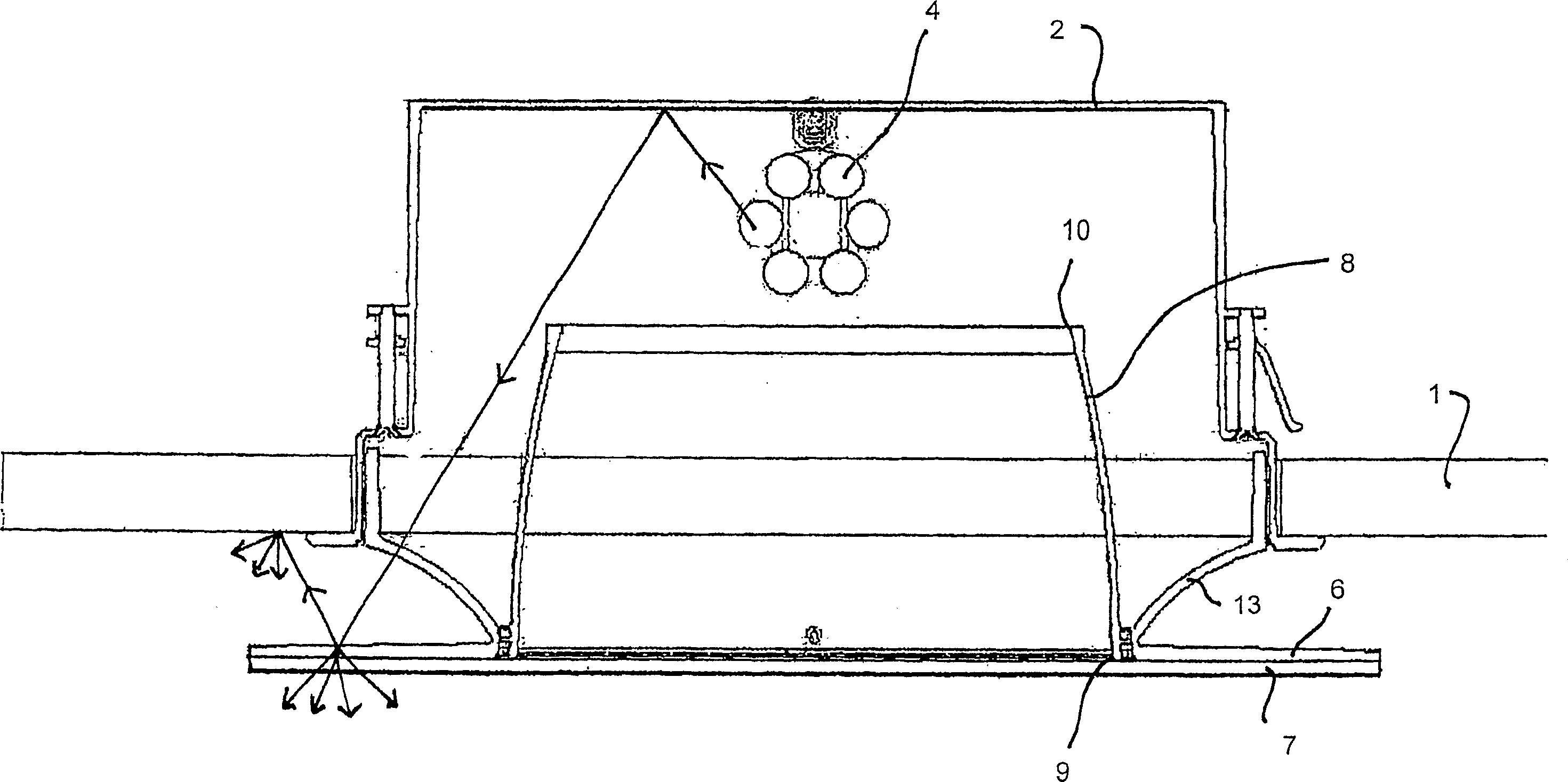
[0036] Such as figure 1 As shown, a substantially cylindrical lampshade 2 is fixed in the ceiling 1 of the room, the lower part of the lampshade 2 is open, and a light source seat 3 with a light source 4 inserted therein is arranged in the area of ​​the base of the lampshade.

[0037] In the edge region of the lampshade opening, a translucent or transparent cylindrical element 5 is connected to the inside of the lampshade 2, the cylindrical element 5 forming an additional light exit region. The cylindrical element 5 protrudes from the lampshade 2 in the main lighting direction A, and at the end remote from the lampshade 2 has a flange 6 extending parallel to the room ceiling 1, the flange 6 is circular and forms the reflective element of the present invention.

[0038] A transparent plate 7 is connected to the bottom of the flange 6 , the transparent plate 7 extends parallel to the bottom of the flange 6 , and the diameter of the transparent plate 7 is equal to the outer diame...


PUM


Abstract

The invention relates to a built-in lamp comprising a holder for fastening in an installation surface, in particular in a room ceiling, a bulb fitting and a reflector, wherein the reflector consists of at least a first reflector region which is followed in the direction of illumination by a second reflector region which is releasable from the first reflector region to permit a bulb change.

Description

technical field [0001] The invention relates to a built-in lamp with a bracket, a light source base and a reflector which can be fixed on the installation surface, especially the ceiling of a room. Background technique [0002] Recessed luminaires of this type are known in the prior art in a number of different configurations in which the light source and reflector of known dimmed luminaires are arranged so that the light source will not be visible from a certain viewing angle , because it will not have a dazzling effect. However, the result of avoiding the glare effect is that this lighting method will still leave a large area of ​​the ceiling area that should be illuminated, and the relationship between the light source and the illuminated area that people can naturally perceive will be lost, because the identification It is not clear which light source is emitting the light that illuminates the area. [0003] In the prior art, part or all of the frosted glass is fixed o...

Claims


Application Information

Patent Timeline
IPC IPC(8): F21S8/02F21V7/00F21V17/10F21V17/14F21V17/16
CPCF21V17/107F21Y2103/025F21V17/164F21V7/0016F21S8/02F21V17/10F21V7/0025F21S8/026F21Y2103/00F21V17/105F21V17/14F21Y2113/00F21Y2103/37
Inventor 哈特姆特·S·英格尔
Owner 哈特姆特 S 英格尔
Why Eureka
Try Eureka