
Camera debugging method and device, and electronic equipment

A debugging method and camera technology, applied in TV, electrical components, color TV, etc., can solve problems such as unfavorable image analysis and poor image quality, and achieve the effect of good quality and good lighting environment

Active Publication Date: 2021-01-05
SHENZHEN HANGSHENG ELECTRONICS
View PDF9 Cites 3 Cited by
  • Summary
  • Abstract
  • Description
  • Claims
  • Application Information

AI Technical Summary

Problems solved by technology

[0003] The purpose of the present invention is to solve the problem of poor image quality obtained by the camera in the prior art, which is not conducive to image analysis, and provides a camera debugging method, device and electronic equipment

Method used


Image

  • Camera debugging method and device, and electronic equipment
  • Camera debugging method and device, and electronic equipment
  • Camera debugging method and device, and electronic equipment

Examples


Embodiment Construction

[0058] In order to make the purpose, technical solutions and advantages of the embodiments of the present invention clearer, the technical solutions in the embodiments of the present invention will be clearly and completely described below in conjunction with the drawings in the embodiments of the present invention. Obviously, the described embodiments It is a part of embodiments of the present invention, but not all embodiments. Based on the embodiments of the present invention, all other embodiments obtained by persons of ordinary skill in the art without creative efforts fall within the protection scope of the present invention. In the case of no conflict, the following embodiments and features in the embodiments can be combined with each other.

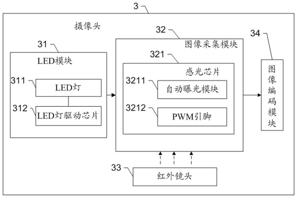
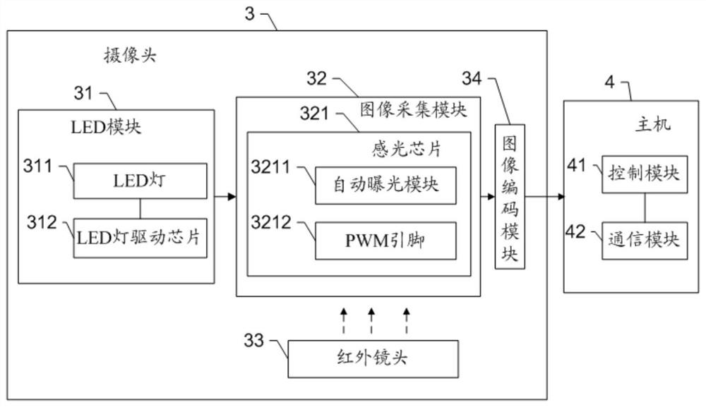
[0059] Such as figure 1 as shown, figure 1 It is a structural diagram of a camera provided by an embodiment of the present invention. The camera 3 includes a photosensitive chip 321 supporting PWM adjustable wave and global expo...


PUM


Abstract

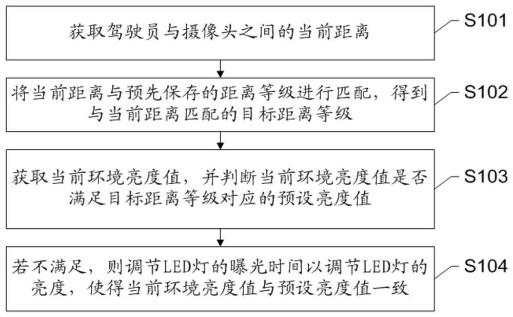
The invention discloses a camera debugging method and device, and electronic equipment. The camera debugging method comprises the following steps of: acquiring a current distance between a user and acamera; matching the current distance with a pre-stored distance grade to obtain a target distance grade matched with the current distance; acquiring a current environment brightness value, and judging whether the current environment brightness value meets a preset brightness value corresponding to the target distance grade or not; and if not, adjusting the exposure time of an LED lamp to adjust the brightness of the LED lamp, so that the current ambient brightness value is consistent with the preset brightness value. According to the camera debugging method and the device, the exposure time of the LED lamp in the camera can be adjusted to adjust the brightness of the LED lamp, so that an excellent illumination environment can be provided for the camera, the camera can acquire images withexcellent quality, and the problems of poor image quality and inconvenience in image analysis in the prior art are solved.

Description

technical field [0001] The invention relates to the technical field of vehicle equipment, in particular to a camera debugging method, device and electronic equipment. Background technique [0002] As we all know, some people will have fatigue driving, inattention, phone calls and other situations that affect traffic when driving, which is prone to traffic accidents. In order to supervise the above-mentioned behaviors of drivers, cameras are generally installed on the car The driver's image is collected through the camera, and the driver's driving behavior is recognized through image processing. However, the traditional camera image acquisition module adopts the progressive exposure method, which will lead to the overall exposure time being too long, which means that the shutter is opened for too long, and the head shakes or people blink frequently in the image, so in Misjudgment will occur when the image algorithm of each frame is captured during image analysis. The traditi...

Claims


Application Information

Patent Timeline
IPC IPC(8): H04N5/235
CPCH04N23/71H04N23/73H04N23/74
Inventor 马勇
Owner SHENZHEN HANGSHENG ELECTRONICS
Learn More