Pressure safety valve

A safety valve and pressure technology, applied in the field of pressure safety valves, can solve problems such as invalid pillars and easy damage

Inactive Publication Date: 2007-03-14
MINE SUPPORT PRODS CORP
View PDF0 Cites 2 Cited by
  • Summary
  • Abstract
  • Description
  • Claims
  • Application Information

AI Technical Summary

Problems solved by technology

If the valve is on the outside surface of the strut then it is easily damaged and the strut may then become ineffective

Method used


Image

  • Pressure safety valve
  • Pressure safety valve
  • Pressure safety valve

Examples


Embodiment Construction

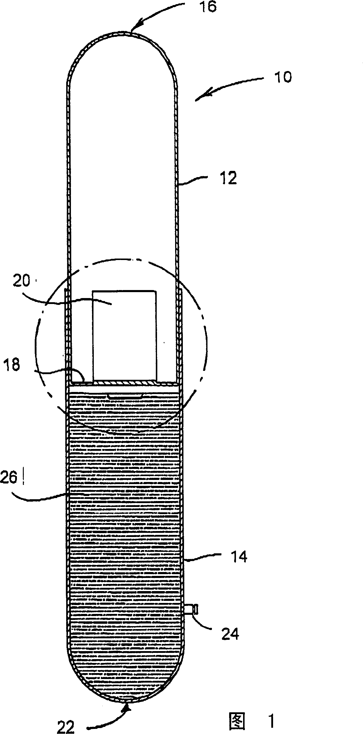
[0013] The figures show a support 10 of the type used, for example, in underground excavations to provide support between a roof wall and an opposing ground wall, the support comprising a first tubular member 12 and a second tubular member 14, so that The second tubular member is telescopically connected to the first member.

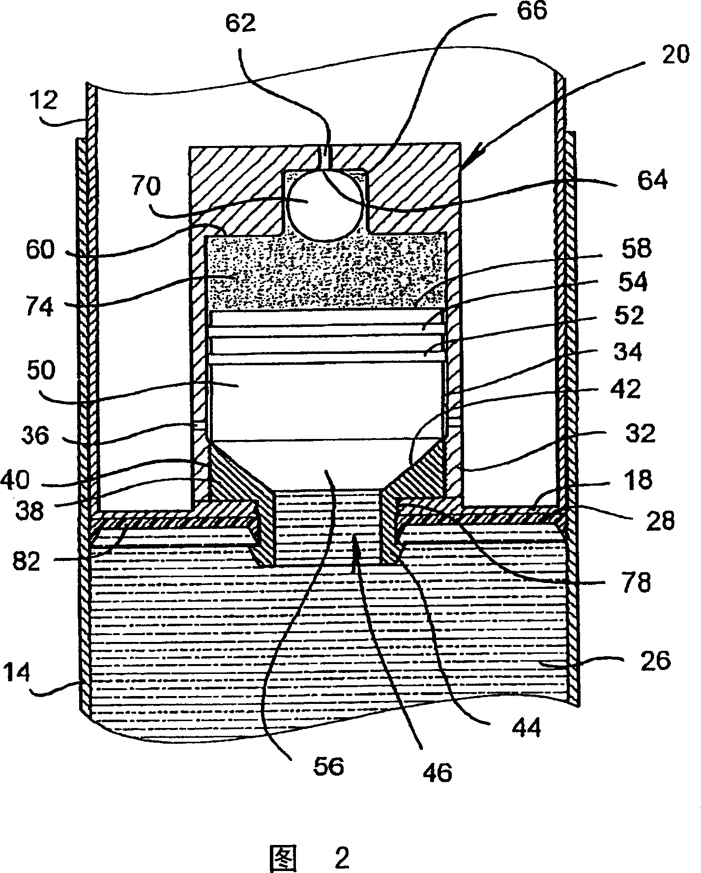
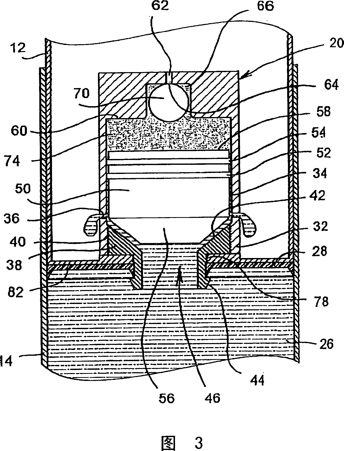
[0014] Member 12 has a circular upper end 16 to which a disc 18 is secured. A valve 20 shown in more detail in Figures 2 and 3 is secured to the disc.

[0015] Tubular member 14 has a circular lower end 22 and a one-way injection valve 24 affixed to the side wall. A volume 26 is defined within the second member 14 . A seal 28 engaging the disc 18 faces the volume 26 and provides a sealed interface between the components 12 and 14 .

[0016] Valve 20 includes a housing 32 defining a chamber 34 therein. A plurality of outlets 36 are formed through the wall of the housing. The valve seat 38 has threads 40 which threadably engage complementary threads i...


PUM


Abstract

A pressure relief valve comprises shell, cavity set in shell, inlet connected to the cavity, at least one outlet of cavity, valve base s between inlet and outlet, valve component in cavity, at least sealing between valve component and cavity. Valve component has the first end and the second end relative to another and can move between the first position and the second position in cavity. On the first position the first end and valve base join tightly so as to prevent fluid flow between inlet and outlet. On the second position the second end and valve base is not joined together so as to permit fluid flow between inlet and outlet. The invention also contains pressurized gas-sealing room with various cubages, which is limited by the second end of valve component in cavity, the channel extended through shell to sealing room, which has the internal opening, locative structure around internal opening, sealing plug connected with locative structure. Said sealing plug contact internal opening tightly.

Description

technical field [0001] The present invention relates to a pressure relief valve for use with a retractable support column suitable for use in underground excavations, such as mines. technical background [0002] Pressure relief valves are typically incorporated into hydraulic struts to allow the struts to retract under load. If the valve were on the outer surface of the strut, it would be easily damaged and the strut might then become ineffective. Contents of the invention [0003] The present invention relates to a pressure relief valve mountable on the inner surface of a strut. The invention also relates to a strut incorporating a valve of the aforementioned type. [0004] The present invention provides a pressure safety valve comprising: a housing, a chamber within the housing, an inlet connected to the chamber, at least one outlet from the chamber, located between said inlet and said outlet a valve seat, a valve member located in the chamber, at least one seal betwe...

Claims


Application Information

Patent Timeline
IPC IPC(8): E21D15/51E21D17/00
Inventor F·迪马特奥
Owner MINE SUPPORT PRODS CORP
Why Eureka
Try Eureka