Supercharge Your Innovation With Domain-Expert AI Agents!

Manufacture method for motor and motor

A manufacturing method and motor technology, which can be used in electrical components, electromechanical devices, etc., and can solve problems such as difficulties

Inactive Publication Date: 2007-03-28
SANKYO SEIKI MFG CO LTD
View PDF1 Cites 1 Cited by
  • Summary
  • Abstract
  • Description
  • Claims
  • Application Information

AI Technical Summary

Problems solved by technology

In this case, when the bearing holder is fixed to the outer stator core of the anti-output side stator group, since the protrusions interfere, the outer stator core, Coils and inner stator core are difficult

Method used


Image

  • Manufacture method for motor and motor
  • Manufacture method for motor and motor
  • Manufacture method for motor and motor

Examples


Embodiment Construction

[0027] Embodiments of the present invention will be described below with reference to the drawings.

[0028] (whole structure)

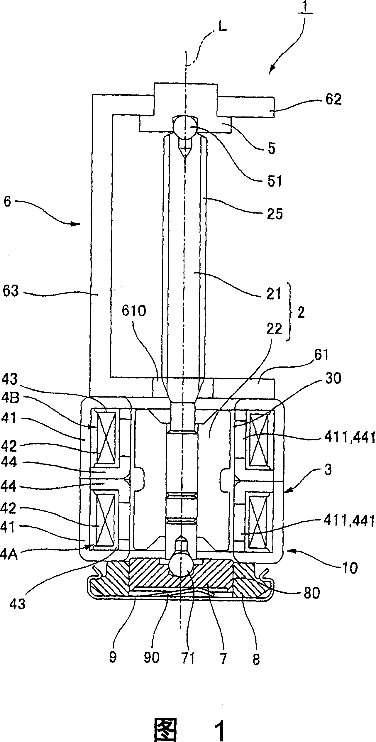
[0029] Fig. 1 is a sectional view of a stepping motor to which the present invention is applied.

[0030] As shown in the figure, the motor 1 of this form is a small PM-type stepping motor used in digital cameras, digital video cameras, FDDs, ODDs, etc., and has a rotor 2 including a rotating shaft 21, including a coaxial arrangement of the rotor. The stator 3 of the hole 30 is arranged in the rotor on the base end side of the rotor 2 .

[0031] The stator 3 includes an anti-output-side stator group 4A and an output-side stator group 4B, and these stator groups 4A, 4B are arranged in a two-phase configuration overlapping each other in the motor axis L direction. The stator groups 4A and 4B both have: an outer stator core 41; an annular bobbin 43 wound with a coil 42; The end faces of the sub-cores 44 are fixed. A plurality of pole teeth 411 , 441...


PUM


Abstract

In a stepping motor (1), three remaining protrusions can be spot-welded even if one of four protrusions is located in a position in which it can not be welded to the motor attachment plate (6) since four spot welding protrusions for protruding toward the output are formed in the outer stator core (41) of the stator group (4B). There is no problem for assembling even if four protrusions (452) are located in the outer stator core (41) of the stator group (4B) since all of four protrusions are spot-welded to a bearing holder (8) and the outer stator core (41) of the stator group (4A). The stator groups (4A, 4B) can comprise the identically structured component. Provided is a stepping motor for enabling spot welding in at least three positions without a design change in an outer stator core even if an attachment angle between a motor attachment plate and a stator is changed, and enabling an identically structured component to be used for the outer stator core in an output stator group and an opposite output stator group.

Description

technical field [0001] The present invention relates to a method for manufacturing an electric motor and the electric motor. More specifically, it relates to a technique for fixing a bearing cage and a motor mounting plate to a stator. Background technique [0002] In stepping motors used in digital cameras, digital video cameras, FDDs, ODDs, etc., a rotor is generally arranged in a cylindrical stator inside a rotor arrangement hole opened in the axial direction of the motor, and one end of the rotating shaft is supported by a bearing through a ball. Here, the bearing is inserted into the through hole of the bearing holder, and is biased toward the rotating shaft by the plate spring portion of the pressure-increasing member arranged on one end side of the bearing holder. In addition, two claws extend from the booster applying member, and an engaging portion is formed on the output-side end surface of the bearing holder. When the pressure applying member is rotated, the eng...

Claims


Application Information

Patent Timeline
IPC IPC(8): H02K37/24
Inventor 岩岛伸悟
Owner SANKYO SEIKI MFG CO LTD
Features
  • R&D
  • Intellectual Property
  • Life Sciences
  • Materials
  • Tech Scout
  • Unparalleled Data Quality
  • Higher Quality Content
  • 60% Fewer Hallucinations
Learn More