Steam turbine exhaust diffuser

An exhaust diffuser, steam turbine technology, applied in the direction of machine/engine, mechanical equipment, engine components, etc., can solve problems such as unfavorable pressure drop, loss, etc.

Inactive Publication Date: 2007-04-11
GENERAL ELECTRIC CO
View PDF0 Cites 10 Cited by
  • Summary
  • Abstract
  • Description
  • Claims
  • Application Information

AI Technical Summary

Problems solved by technology

The vapor flow path is thus tortuous, causing losses and unfavorable pressure drops

Method used


Image

  • Steam turbine exhaust diffuser
  • Steam turbine exhaust diffuser
  • Steam turbine exhaust diffuser

Examples


Embodiment Construction

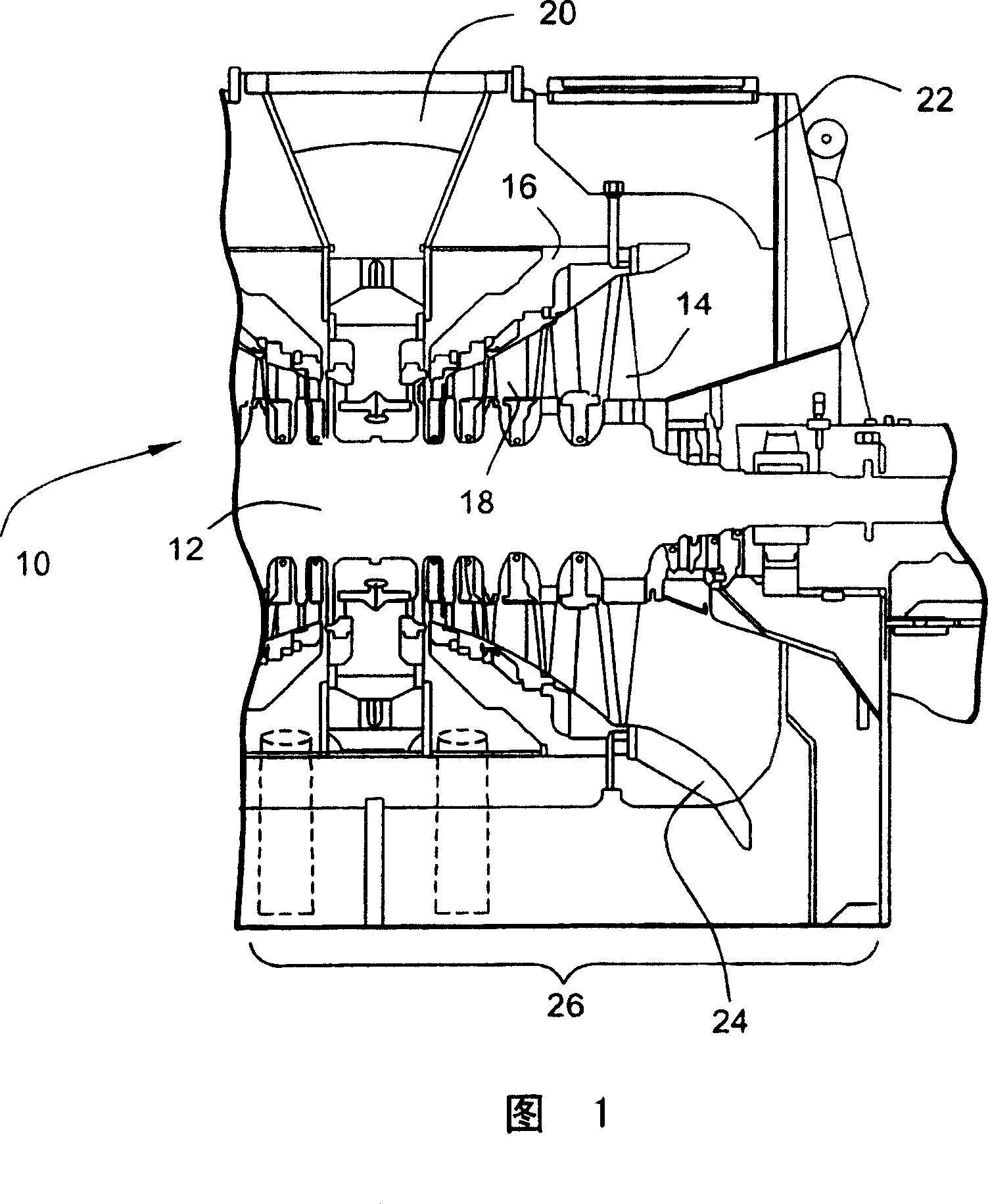
[0007] Referring now to the drawings, and in particular to FIG. 1 , there is illustrated a portion of a steam turbine 10 including a rotor 12 carrying a plurality of turbine blades 14 . A plurality of partitions 18 are installed on the inner shell 16 . A centrally located generally radial steam inlet 20 applies steam to each of the turbine blades and stator blades on axially opposite sides of the turbine to drive the rotor. The stator blades of the diaphragm 18 and the axially adjacent blades 14 make up the stages of the turbine forming the flow channels. It will be appreciated that steam is withdrawn from the last stage of the turbine to flow into a not shown condenser.

[0008] Also shown in Figure 1 is an outer exhaust shroud 22 which surrounds and supports the inner casing of the turbine as well as other components such as bearings. In FIG. 1 , the turbine includes a steam deflector 24 for directing steam exiting the turbine into an outlet 26 for flow to one or more cond...


PUM


Abstract

An axial flow steam turbine includes an exhaust diffuser in the form of a volute (40) for diffusing the exhaust steam and turning the exhaust steam from a generally axial flow direction to a generally radial direction. The volute exit (46) may be at the bottom or to one side of the steam turbine. The volute and casing are independently mounted relative to one another on a foundation with a flexible joint therebetween.

Description

technical field [0001] The invention relates to a steam turbine, in particular to a volute exhaust diffuser. Background technique [0002] In existing steam turbines, the inner casing of the steam turbine, such as the dual flow exhaust, has a surrounding exhaust shroud that is bisected and extends vertically along opposite sides and ends of the turbine. This large box-like configuration houses the entire low pressure section of the turbine. The steam outlet of the turbine is generally conical, and the steam exhaust is redirected from a generally axially extending flow direction to a flow direction 90 degrees relative to the axial flow direction. The 90 degree flow direction can be in any plane, downward, upward or lateral. The existing exhaust hood of the steam turbine therefore constitutes a large rectilinear configuration at the outlet end of the conical section for bending and diverging the steam flow at right angles. The steam flow path is thus tortuous, causing losse...

Claims


Application Information

Patent Timeline
Patent Type & Authority Applications(China)
IPC IPC(8): F01D25/30
CPCF01D25/30F05D2220/31F05B2220/301F01D25/28
Inventor E·沙劳
Owner GENERAL ELECTRIC CO
Why Eureka
Try Eureka