

Hollow four plane tie-in
A flat, hollow technology, applied in the direction of connection, conductive connection, clamping/spring connection, etc., can solve the problems of high cost of conversion fittings, uneven current distribution, blown tube busbar, etc., to save non-ferrous metals, save energy, The effect of reducing consumables
Inactive Publication Date: 2007-05-23
罗志昭
View PDF1 Cites 1 Cited by
- Summary
- Abstract
- Description
- Claims
- Application Information
AI Technical Summary
Problems solved by technology
[0002] The existing conductive pipe busbar joint (patent number: 01215457.1) has the following disadvantages in the actual installation process: since the conductive pipe busbar is circular, it is necessary to install conversion fittings during the connection with the equipment, from a round surface to a plane, through Rectangular conductors to connect with other equipment
1. The connection between the pipe busbar and the equipment needs to be equipped with conversion fittings, which is costly, wastes materials, and consumes energy
2. In the original joint, only two conductive plane conductors are split, and there will be uneven current distribution when the current is transmitted. One of the conductive plane conductors has a small overcurrent, and the other one has a large overcurrent. The big side will generate high temperature
3. The connection between the end of the pipe busbar and the conversion fitting will generate contact resistance. Due to the existence of contact resistance, in the case of high current transmission, the end of the pipe busbar and the conversion fitting will generate excessive heat. The greater the heat, the higher the resistance , the more serious the heat is, the higher the temperature will cause the pipe busbar to be blown, short circuit between phases, short circuit to ground or cause a fire and cause a greater accident
Method used
View moreImage
Smart ImageViewing Examples

Examples
Embodiment Construction
[0009] The specific embodiments of the present invention will be further described below in conjunction with the accompanying drawings.
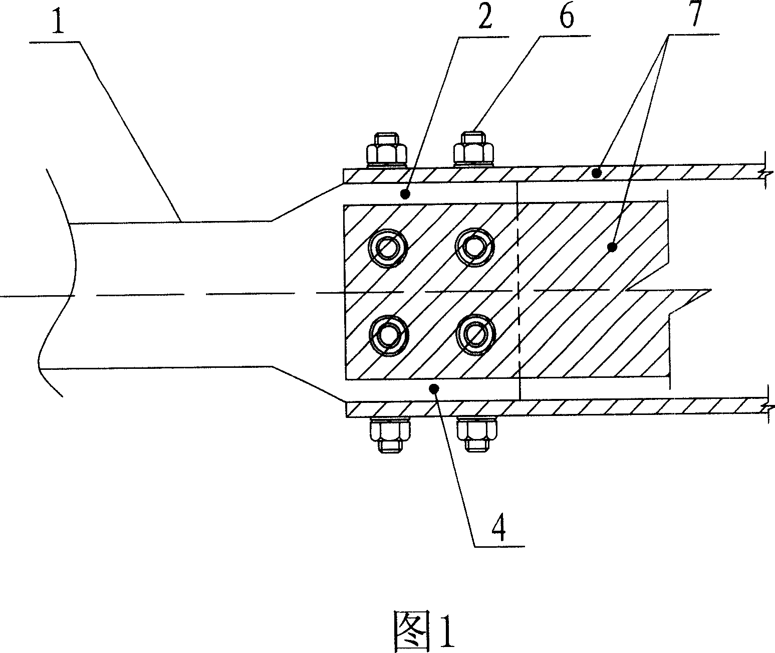
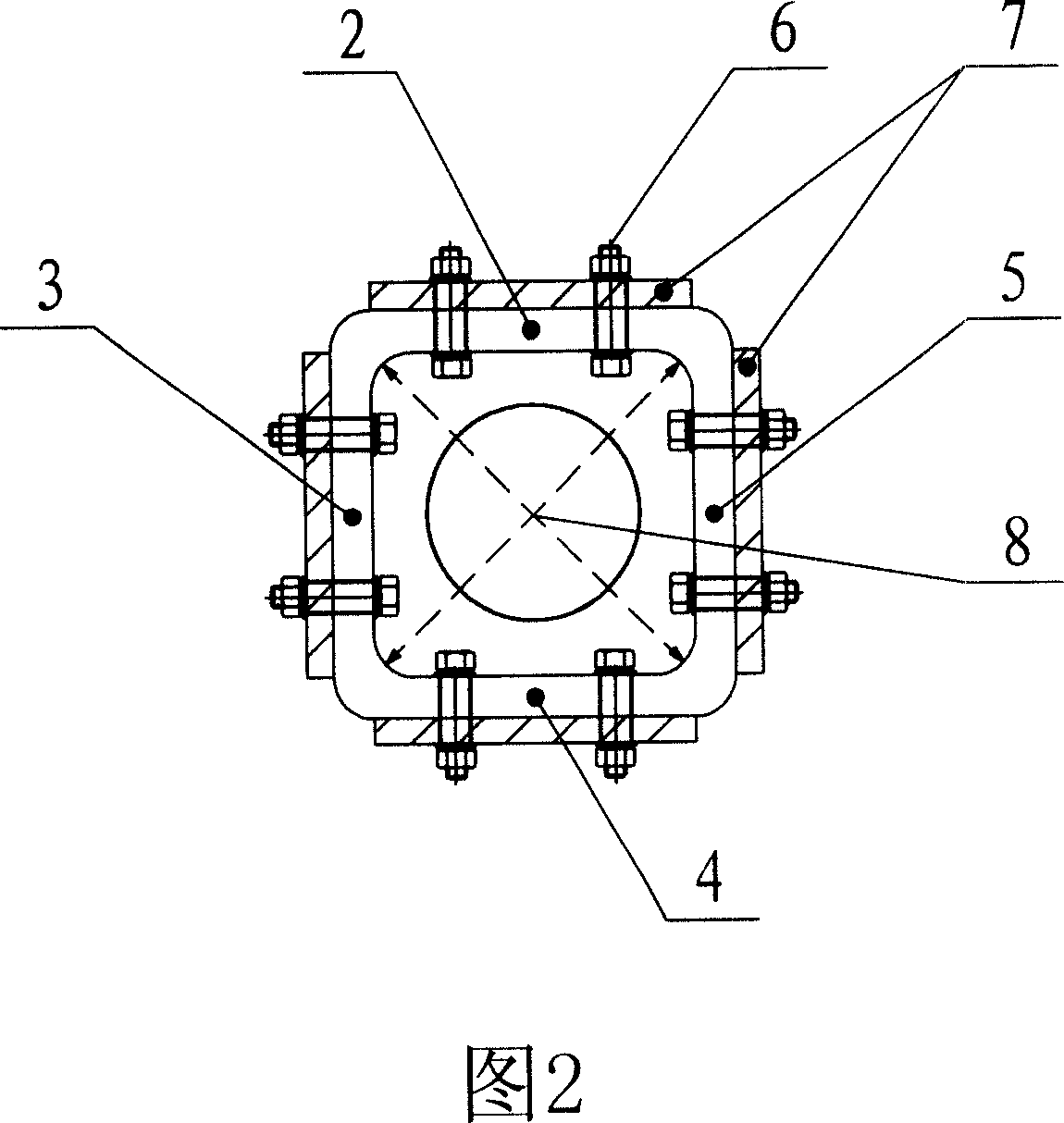
[0010] As shown in Figure 1, the hollow four-plane joint of the present invention is a hollow four-plane joint in which the end of the tube bus bar is formed by stamping and forming hollow four conductive planes. The four conductive planes are connected, and the four conductive planes are connected. There is a certain heat dissipation space between the planes, and the 4 conductive planes formed by this stamping are connected with other devices through rectangular conductors or soft connections, which form a heat-dissipating hollow four-plane joint.
Login to View More PUM
 Abstract
The invention relates to a hollow four-face connector, wherein it end diameter of tube main line is punched into hollow four-plane conductive plane; and it is integral without connecting part, it has low contact resistance, to avoid high temperature at end.
Description
Technical field [0001] The hollow four-plane joint of the present invention is particularly suitable for the connection of the busbar of the conductive tube that transports the power frequency large current and the equipment. The current carrying capacity is large, the temperature rise is low, the mechanical strength is high, and the operating safety factor is improved. Background technique [0002] The existing conductive tube busbar connector (patent number: 01215457.1) has the following shortcomings in the actual installation process: Since the conductive tube busbar is round, it is necessary to install conversion fittings during the connection with the equipment, and the round surface is converted into a flat surface. The rectangular conductor is connected to other equipment. 1. The connection between the tube bus and the equipment needs to be equipped with conversion fittings, which is costly, wastes materials and consumes energy. 2. In the original join...
Claims
Login to View More Application Information
Patent Timeline
 Patent Type & AuthorityApplications(China)
IPC IPC(8): H01R4/38H01R4/00
Inventor罗志昭
Owner罗志昭