Contact terminals, electrical connectors and electronic equipment

A technology for contact terminals and electrical connectors, which is applied in the direction of connection, contact parts, parts of connection devices, etc., can solve the problems of small terminal holding force, unreliable contact, scattered contact parts, etc., to increase the contact area and improve The service life and the effect of increasing the terminal current carrying capacity

Active Publication Date: 2022-07-01
SHENZHEN LINKEXCEL PRECISION TECH LTD
View PDF0 Cites 0 Cited by
  • Summary
  • Abstract
  • Description
  • Claims
  • Application Information

AI Technical Summary

Problems solved by technology

In order to ensure the contact resistance, the density of wire spring winding must be increased, which also leads to the fact that the wire spring contact scheme cannot be used in small-sized terminals
[0009] 2. In order to ensure the contact area, the wire spring solution cannot use large-diameter wires to wind the contacts, so the insertion and withdrawal force of the wire spring terminal is much smaller than that of the torsion spring terminal.
Although a small insertion force can improve the service life of the terminal, at the same time, because the holding force of the terminal is too small, there may be a problem of discontinuous contact of the terminal, especially in the scene of vibration and shock in a heavy-duty environment
[0010] 3. The wire spring uses a wire to wind the contact piece. If there is a disconnection phenomenon during use, the whole contact piece will be scattered and the contact will no longer be reliable.
In addition, after the winding of the contact piece is completed, it is necessary to manually join the two ends of the wire spring, which will affect the production capacity and cannot meet the large demand of the market.

Method used


Image

  • Contact terminals, electrical connectors and electronic equipment
  • Contact terminals, electrical connectors and electronic equipment
  • Contact terminals, electrical connectors and electronic equipment

Examples


Embodiment 1

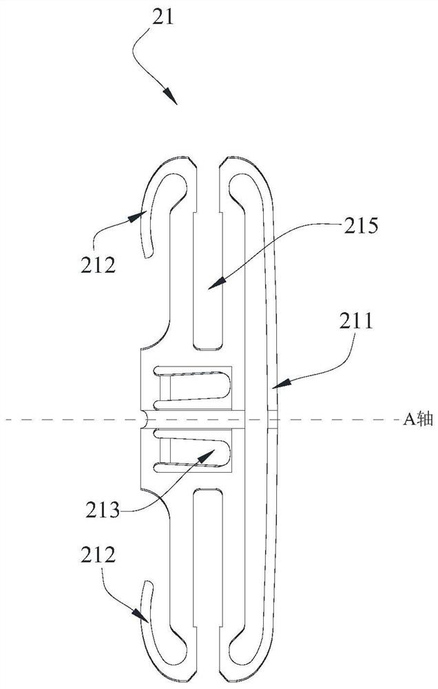
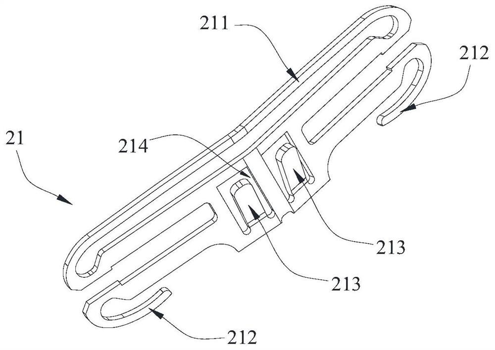
[0051] Contact terminals, which are used in electrical connectors. Please refer to Figure 1-5 As shown, the contact terminal mainly includes a first contact piece 21 and a first bracket 30 . The first contact piece 21 is provided with a first contact arm 211 and a second contact arm 212, the first contact piece 21 is preferably formed by punching, and the punching direction is perpendicular to the direction of the first contact arm 211 or the second contact arm 212 , that is, the thin edges on both sides of the first contact piece 21 serve as the first contact arm 211 and the second contact arm 212 respectively.

[0052] Using the first contact piece 21 with the punching method and the punching direction perpendicular to the direction of the first contact arm 211 or the second contact arm 212 can avoid the problem that the width and spacing of the contact pieces cannot be reduced due to factors such as mold manufacturing, and can ensure The insertion force of the male and f...

Embodiment 2

[0066] The second embodiment shows another structure of the contact terminal. It realizes that the end face of the contact terminal in contact with the male terminal is a hyperboloid by twisting.

[0067] Please refer to Figure 7-9 As shown, for the sake of distinction, the contact piece of the second embodiment is called the second contact piece 24 (corresponding to the first contact piece in the first embodiment), and the side of the second contact piece 24 in contact with the male terminal is called the third contact piece 24 For the contact arm 241 (corresponding to the first contact arm in the first embodiment), the side of the second contact piece 24 in contact with the main body of the female terminal is referred to as the fourth contact arm 242 (corresponding to the second contact arm in the first embodiment).

[0068] In the second embodiment, the connection portion between the third contact arm 241 and the fourth contact arm 242 is twisted by a certain angle, so th...

Embodiment 3

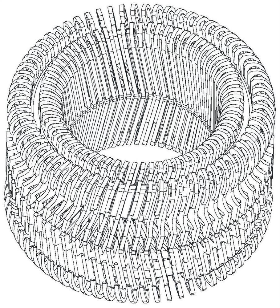
[0073] The third embodiment shows the structure of an electrical connector. It mainly includes a first connector female terminal 100 . Please refer to Figure 10-13 As shown, a cylindrical first connector receptacle 100 is shown, the first connector receptacle 100 includes a first receptacle body 10 , a first contact terminal 20 and a plug 40 .

[0074] The first female terminal body 10 defines an accommodating space, the first contact terminal 20 is installed in the accommodating space, and the plug 40 is blocked at the end of the accommodating space to prevent the first contact terminal 20 from being placed in the accommodating space. Axial movement in the first female terminal body 10 .

[0075] The first contact terminal 20 may adopt any structural form of the first embodiment or the second embodiment. E.g Figure 12 and Figure 13 It is shown that the contact terminal method of the first embodiment is used, and the bent portion provided on the second contact arm of ...


PUM


Abstract

The invention discloses a contact terminal, which comprises a bracket and a plurality of contact pieces, the bracket strings together the plurality of contact pieces so that the plurality of contact pieces form an annular structure, and the contact piece includes a first contact arm and a second contact arm , the first contact arm is located at the inner side of the annular structure, the second contact arm is located at the outer side of the annular structure, and the first contact arm is a hyperboloid structure. The invention also discloses an electrical connector and an electronic device including the above-mentioned contact terminal. In the embodiment of the present invention, through the annular structure composed of a plurality of contact pieces, the electrical contact is changed from the line contact of the wire spring to the surface contact, which increases the contact area, effectively reduces the contact resistance, and increases the terminal current carrying at the same time. The spring has the characteristics of low insertion force, so as to achieve the dual purpose of increasing the current carrying capacity and improving the service life.

Description

technical field [0001] The present invention relates to the technical field of connectors, in particular to a contact terminal, an electrical connector and an electronic device. Background technique [0002] With the needs of social development, more stringent requirements have been put forward for electrical connectors, which are mainly reflected in two aspects: First, the current-carrying capacity of terminals (male terminals and female terminals) is required to be higher, especially for energy storage and new Energy and other application scenarios that have higher requirements on product weight and size; second, higher requirements on the service life of terminals, such as battery swapping technology or new energy charging connectors and other application scenarios that require frequent plugging and unplugging. [0003] In order to meet the demand for contact terminals of electrical connectors, there are currently two main types of products in the world. The first type is...

Claims


Application Information

Patent Timeline
Patent Type & Authority Patents(China)
IPC IPC(8): H01R13/02H01R13/629
CPCH01R13/02H01R13/629
Inventor 白云华汪晓华
Owner SHENZHEN LINKEXCEL PRECISION TECH LTD
Why Eureka
Try Eureka