Electric apparatus having plural electric parts

a technology of electric components and electric devices, applied in the direction of electrical devices, electromagnetic relay details, printed circuits, etc., can solve the problems of insufficient stability or strength of mounting, inability to connect thin terminals with tuning-fork-shaped terminals, and inability to adapt thin terminals to electric devices, etc., to achieve the effect of reducing the insertion force and facilitating the positioning of terminals at the time of mounting

Inactive Publication Date: 2008-03-04
ANDEN CORP
View PDF7 Cites 5 Cited by
  • Summary
  • Abstract
  • Description
  • Claims
  • Application Information

AI Technical Summary

Benefits of technology

[0009]Compared to an electric apparatus, in which the terminals are arranged in a single line, the electric apparatus according to the present invention improves a stability and strength when the electric apparatus is mounted to a junction block, since the terminals are arranged in two or more lines and the plural terminals are arranged in each line. Therefore, the electric apparatus can be mounted to the junction block by being supported stably with the terminals only.
[0012]Therefore, thicker external terminals to be connected to the terminals can be used, since areas around the terminals can be more spacious. As a result, heat generated by the electric parts can be effectively conducted and released to an outside through the thicker external terminals. Therefore, the apparatus is suitable for mounting electromagnetic relays, which generate a large amount of heat.
[0013]Since the terminals on the adjacent two lines are arranged alternately in the terminal arrangement direction, the apparatus according to the present invention can be mounted to the junction block from a terminal arranged at the end by slightly inclining the electric part, a positioning of the terminals at the time of mounting becomes easier. Also, the electric apparatus can be mounted to the junction block with a smaller insertion force in total, because the terminals can be inserted one by one.

Problems solved by technology

In this case, since many terminals are arranged in the single line, there is a problem that a sufficient stability or strength in mounting can not be obtained if the electric apparatus is supported by the terminals only.
Furthermore, the thin terminals are difficult to connect with tuning-fork-shaped terminals (U-shaped terminals) used in the junction block.
Therefore, the thin terminals are not suitable for the electric apparatus to be mounted to the junction block.

Method used


Image

  • Electric apparatus having plural electric parts
  • Electric apparatus having plural electric parts
  • Electric apparatus having plural electric parts

Examples


Embodiment Construction

[0024]An embodiment of an electric apparatus of the present invention will be typically explained with reference to accompanying drawings.

[0025]The electric apparatus contains electromagnetic relays inside the apparatus, and can be used for controlling an electric current conduction of vehicular electric devices such as a head lamp or a wiper motor (neither shown), for example. An up-down direction indicated by the arrows in the accompanying figures shows an arrangement direction of the electric apparatus in the vehicle.

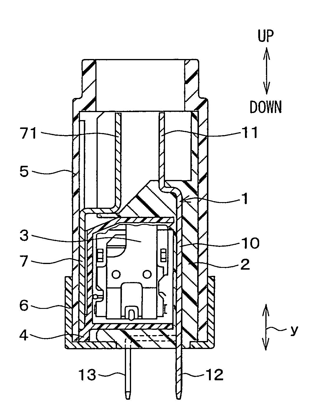
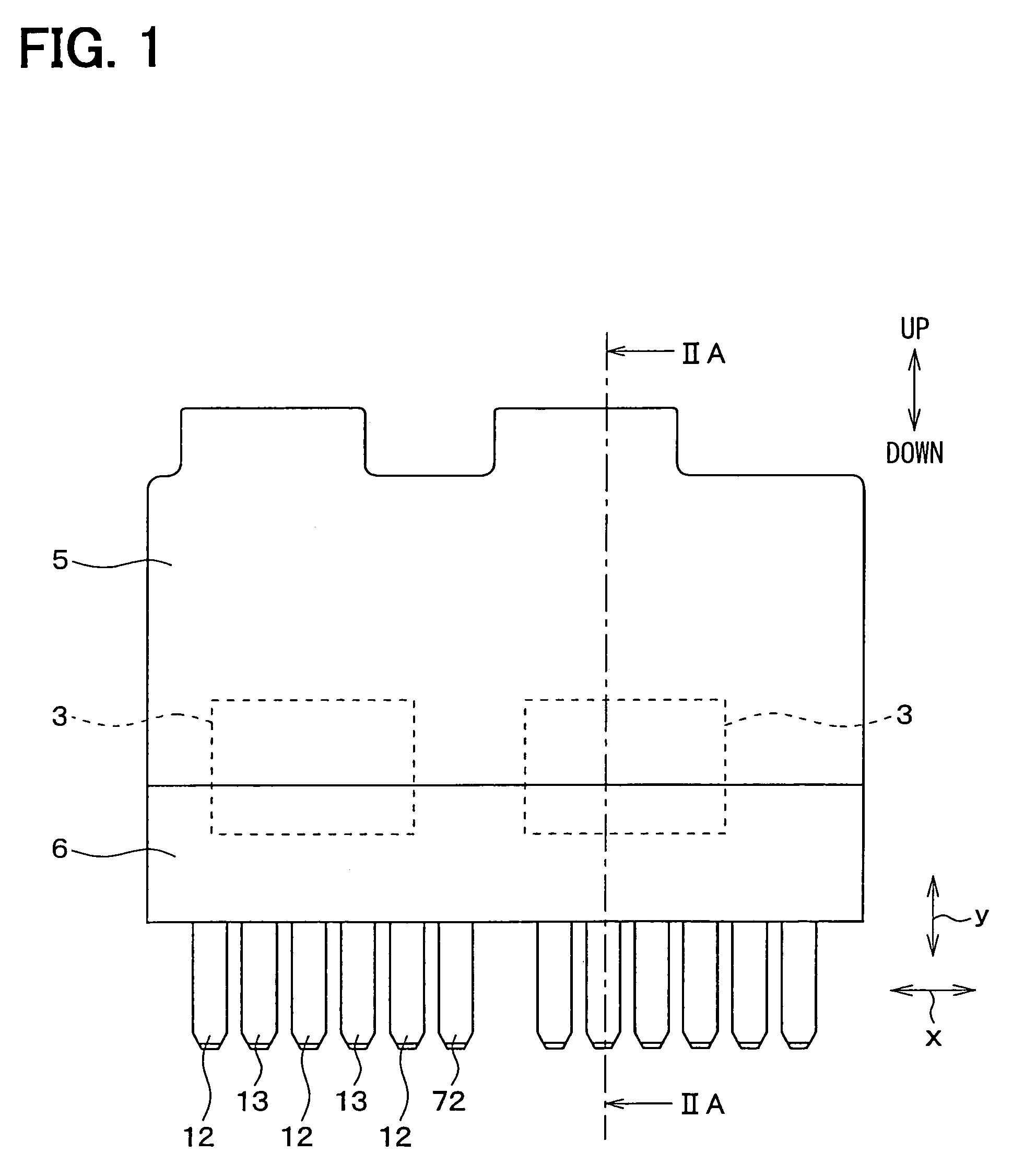
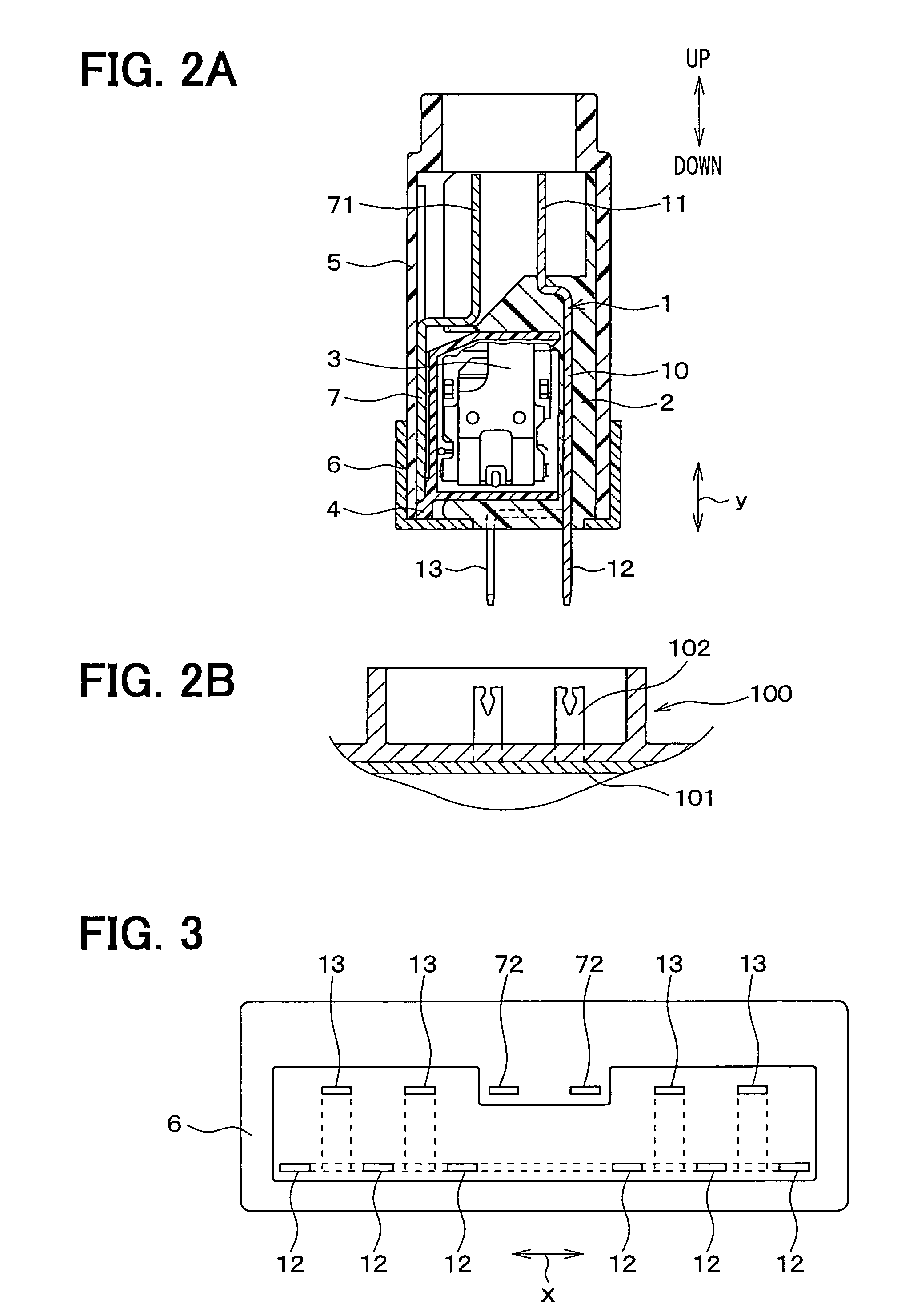
[0026]The electric apparatus has a bus bar 1 formed by press-punching a copper plate, and a part of the bus bar 1 is covered by a resinous layer 2. The resinous layer 2 is formed by resin-molding.

[0027]As shown in FIG. 4, a predetermined wiring pattern (a circuit pattern) is formed on the bus bar 1. The bus bar 1 also includes a main body 10 to which electromagnetic relays 3 are mounted, two fuse terminals 11 projecting from the main body 10 and to be connected to a ...


PUM


Abstract

In an electric apparatus having a bus bar, a plurality of electric parts and a number of terminals connected to external terminals are mounted on the bus bar. The terminals are arranged in two or more lines, plural terminals are arranged in each line. Therefore, a stability and strength in mounting the apparatus to a junction block is improved compared to an apparatus where the terminals are arranged in a single line. The electric apparatus according to the present invention can be mounted to a junction block by being supported with only the terminals of the apparatus.

Description

CROSS REFERENCE TO RELATED APPLICATION[0001]This application is based on Japanese Patent Application No. 2004-306775 filed on Oct. 21, 2004, the contents of which are incorporated herein by reference in its entirety.FIELD OF THE INVENTION[0002]The present invention relates to an electric apparatus, in which a plurality of electric parts are mounted to a single bus bar to form a module. Electrical connections between the electric parts and an exterior are performed through terminals extended from the module. The electric apparatus is suitable for automobiles.BACKGROUND OF THE INVENTION[0003]In a conventional electric apparatus having plural electromagnetic relays mounted to a single bus bar, a number of terminals to be connected to external terminals are mounted to the bus bar and the terminals are arranged in a single line (e.g. JP-A-2002-343216, which is corresponding to U.S. Pat. No. 6,686,821 B2).[0004]To reduce a width dimension of the apparatus (i.e., a dimension in the termina...

Claims


Application Information

Patent Timeline
Patent Type & Authority Patents(United States)
IPC IPC(8): H01R12/00
CPCH01H50/043H01H50/047H01H9/10H01H11/0056H01H49/00H01H50/14H01H2050/049
Inventor SUZUKI, HIROHISA
Owner ANDEN CORP
Why Eureka
Try Eureka