Automated cleaning of cooking apparatus

a technology for cooking equipment and cleaning tools, applied in the field of automatic cleaning of cooking equipment, can solve problems such as accidental injury to users

Active Publication Date: 2018-07-03
TAYLOR COMML FOODSERVICE LLC
View PDF27 Cites 9 Cited by
  • Summary
  • Abstract
  • Description
  • Claims
  • Application Information

AI Technical Summary

Problems solved by technology

Cleaning the plates may require that a user lean over the lower heating plate, which may require waiting until the heating plates cooled prior to cleaning the plates, or, if the plates are not cool, may result in accidental injury to a user.

Method used


Image

  • Automated cleaning of cooking apparatus
  • Automated cleaning of cooking apparatus
  • Automated cleaning of cooking apparatus

Examples


Embodiment Construction

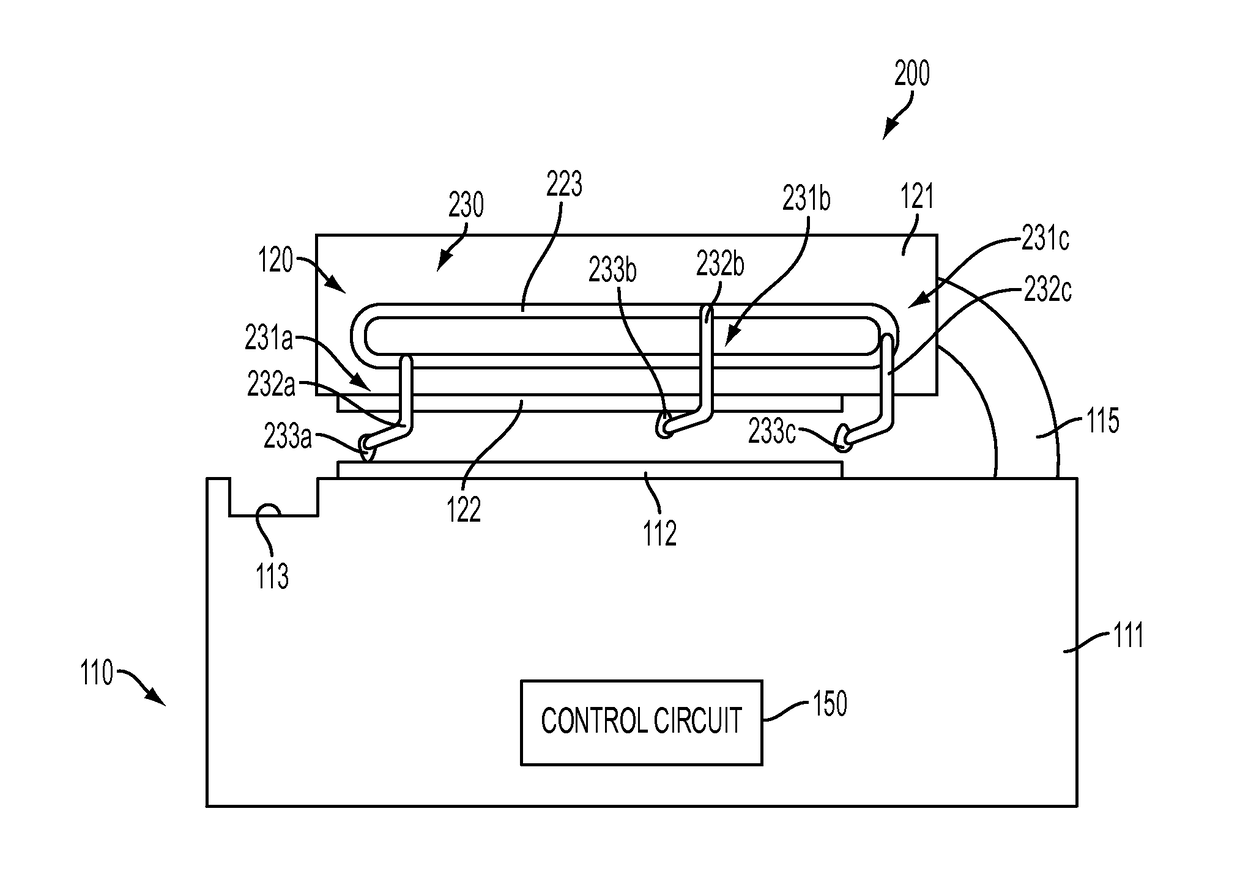
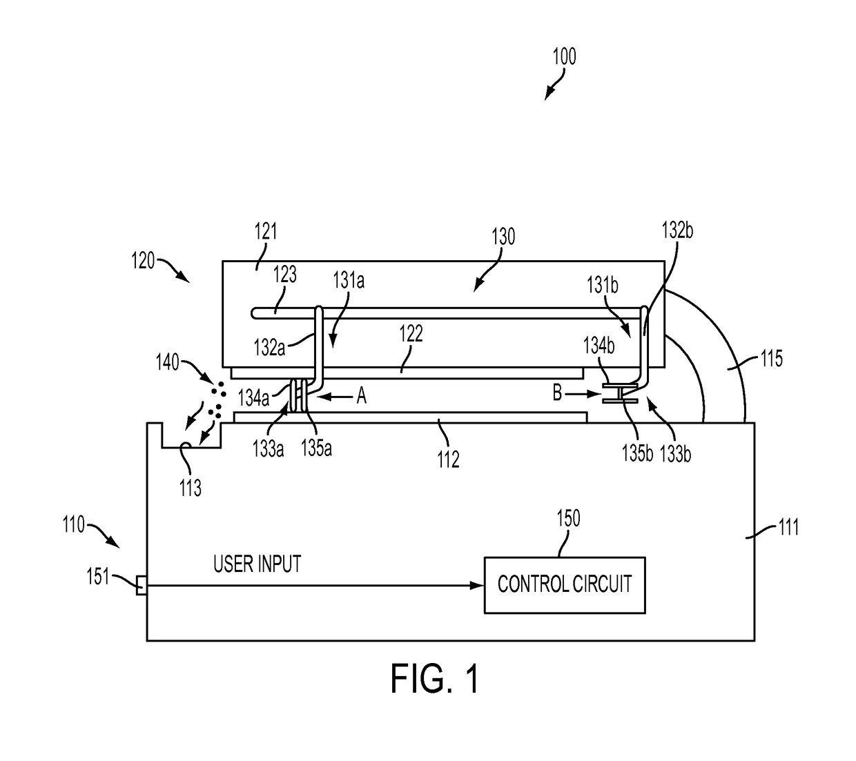
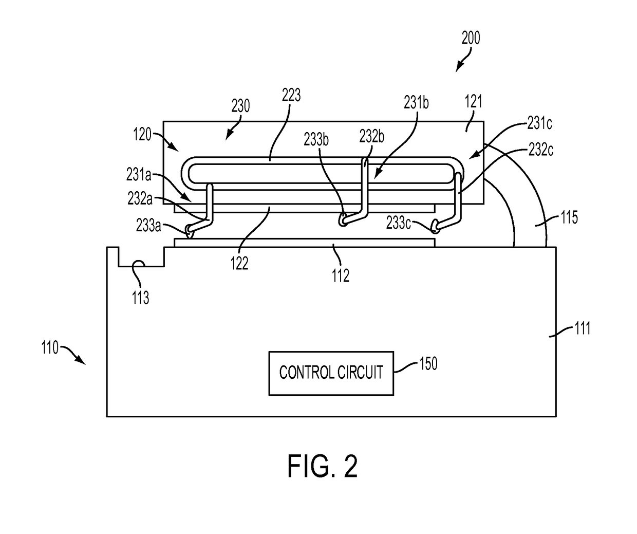
[0012]Conventional grilling apparatuses require an operator to raise and lower an upper heating unit for cooking and cleaning. Embodiments of the invention relate to an automatic cleaning device to clean grilling or cooking surfaces.

[0013]FIG. 1 illustrates a cooking apparatus 100 according to an embodiment of the invention. In one embodiment, the cooking apparatus 100 is a grilling apparatus for grilling food. The cooking apparatus 100 includes a base 110 including a housing 111 that rests on the ground, floor or another surface. The base 110 also includes a first heating plate 112, which may be referred to as a lower heating plate 112. The cooking apparatus 100 also includes an upper heating unit 120 including a housing 121 and an upper heating plate 122.

[0014]In FIG. 1, one configuration of a cooking apparatus 100 is illustrated including a single heating plate 112 on a housing 111 and a single upper heating unit 120. However, embodiments of the invention encompass any configurat...


PUM


Abstract

A cooking apparatus includes a base including a lower heating plate an upper heating unit including an upper heating plate and a cleaning structure configured to move a cleaning blade along at least one of the lower heating plate and the upper heating plate. The apparatus also includes a control circuit configured to control movement of the cleaning blade across the one of the lower heating plate and the upper heating plate.

Description

BACKGROUND OF THE INVENTION[0001]Embodiments of the invention relate to a cooking apparatus, and in particular to a cooking apparatus having an automated cleaning assembly to clean a surface of the cooking apparatus.[0002]Grills for cooking apply heat from a lower heating plate and from an upper heating plate to opposite sides of a food item to decrease cook times and to cook food evenly. In conventional systems, an operator must lift the upper heating plate and manually scrape and clean the upper heating plate and the lower heating plate. Cleaning the plates may require that a user lean over the lower heating plate, which may require waiting until the heating plates cooled prior to cleaning the plates, or, if the plates are not cool, may result in accidental injury to a user.BRIEF DESCRIPTION OF THE INVENTION[0003]Embodiments of the present invention include a cooking apparatus that includes a base including a lower heating plate an upper heating unit including an upper heating pla...

Claims


Application Information

Patent Timeline
Patent Type & Authority Patents(United States)
IPC IPC(8): A47J37/12A21B5/02A47J37/06A47J37/07A21B3/16
CPCA47J37/0786A47J37/0611A21B5/02A21B3/16
Inventor SANDS, JEFFREY L.GLAVAN, RONALD J.NELSON, DENNIS J.FREYMILLER, OTLEY D.
Owner TAYLOR COMML FOODSERVICE LLC
Why Eureka
Try Eureka