Supercharge Your Innovation With Domain-Expert AI Agents!

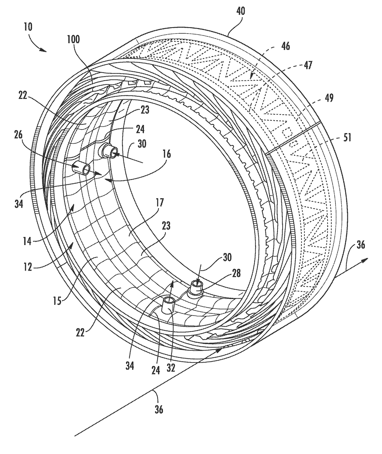
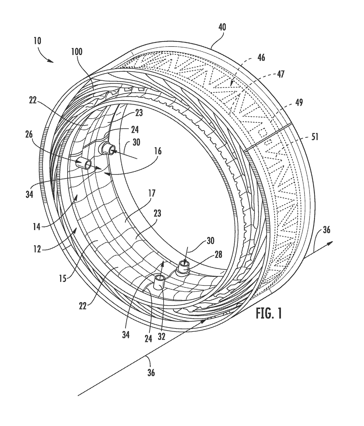
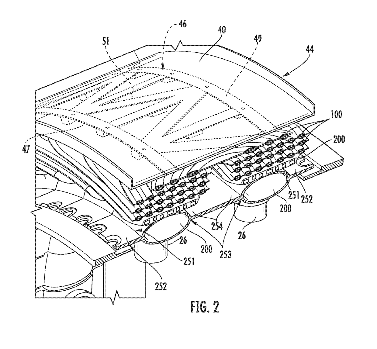
Heat exchanger for embedded engine applications

a technology of heat exchanger and engine, which is applied in the direction of machines/engines, lighting and heating apparatus, laminated elements, etc., can solve the problems of significant impact of fan duct bleed air thrust loss on engine specific fuel consumption, unduly complex current system for heat transfer,

Active Publication Date: 2018-11-13
GENERAL ELECTRIC CO
View PDF26 Cites 14 Cited by
  • Summary
  • Abstract
  • Description
  • Claims
  • Application Information

AI Technical Summary

Benefits of technology

[0007]Aspects and advantages of the invention will be set forth in part in the following description, or may be obvious from the description, or may be learned through practice of the invention.

Problems solved by technology

Use of the heat exchange process is necessary, although, current systems for attaining heat transfers are unduly complex.
By the time the cooler fan duct bleed air reaches the heat exchanger and performs its cooling task, it has lost most of its pressure (thrust potential) due to frictional losses because of various bends and turns of the piping.
The impact of the fan duct bleed air thrust loss on engine specific fuel consumption is significant.
Furthermore, the excessively complex bleed air piping adds significantly to the aircraft weight.

Method used


Image

  • Heat exchanger for embedded engine applications
  • Heat exchanger for embedded engine applications
  • Heat exchanger for embedded engine applications

Examples


Embodiment Construction

[0029]Reference now will be made in detail to embodiments of the invention, one or more examples of which are illustrated in the drawings. Each example is provided by way of explanation of the invention, not limitation of the invention. In fact, it will be apparent to those skilled in the art that various modifications and variations can be made in the present invention without departing from the scope or spirit of the invention. For instance, features illustrated or described as part of one embodiment can be used with another embodiment to yield a still further embodiment. Thus, it is intended that the present invention covers such modifications and variations as come within the scope of the appended claims and their equivalents.

[0030]As used herein, the terms “first”, “second”, and “third” may be used interchangeably to distinguish one component from another and are not intended to signify location or importance of the individual components.

[0031]The terms “upstream” and “downstre...


PUM

PropertyMeasurementUnit
diverging angleaaaaaaaaaa
thicknessaaaaaaaaaa
chord lengthaaaaaaaaaa

Abstract

An annular heat exchanger for a gas turbine engine is provided. The annular heat exchanger can include a first annular ring comprising a first main tube defined by a plurality of transduct segments; a second annular ring comprising a second main tube defined by a plurality of transduct segments and a curvilinear plate defining at least one channel therein that is in fluid communication with a transduct segment of the first main tube and a transduct segment of the second main tube.

Description

FEDERALLY SPONSORED RESEARCH[0001]This invention was made with government support under contact number N00014-10-D-0010 of the Department of the Navy. The government may have certain rights in the invention.FIELD OF THE INVENTION[0002]The present invention relates generally to gas turbine engines and, more particularly, to a heat exchange arrangement in a fan duct of a gas turbine engine for cooling high pressure hot bleed air.BACKGROUND OF THE INVENTION[0003]Many commercial aircraft gas turbine engines employ high pressure hot air bled from the core engine compressor for use by different systems on the aircraft. In particular, the high pressure air is required by a variety of tasks on the aircraft, such as anti-icing and passenger cabin cooling. However, prior to use of the air, the temperature of the air must be lowered to reasonable levels in accordance with the requirements of each specific task.[0004]One current method of cooling the high pressure compressor bleed air is to ext...

Claims


Application Information

Patent Timeline
Patent Type & Authority Patents(United States)
IPC IPC(8): F28F3/00F28F9/02F28D9/00F28D1/02F02C7/18F28D1/047F01D25/12F02C7/141F28D21/00
CPCF28D1/024F02C7/141F02C7/185F28D1/047F28D9/0012F28D9/0018F28F9/026F28F9/0221F01D25/12Y02T50/675F05D2230/31F05D2230/51F05D2300/175F28D2021/0021F28D2021/0026F02C7/18F28D21/00F28F9/26Y02T50/60
Inventor CERNY, MATTHEW ROBERTMENARD, JEFFREY RAYMONDKUPISZEWSKI, THOMASPEGRAM, JOHNATHEN
Owner GENERAL ELECTRIC CO
Features
  • R&D
  • Intellectual Property
  • Life Sciences
  • Materials
  • Tech Scout
  • Unparalleled Data Quality
  • Higher Quality Content
  • 60% Fewer Hallucinations
Learn More