Visualization of packet tracing operation results

a packet tracing and operation result technology, applied in the field of visualizing packet tracing operation results, can solve problems such as difficulty in identifying important details (e.g

Active Publication Date: 2019-02-05
NICIRA
View PDF250 Cites 17 Cited by
  • Summary
  • Abstract
  • Description
  • Claims
  • Application Information

AI Technical Summary

Problems solved by technology

These text logs can be parsed with some work, but identifying important details (e.g., where in the network a particular packet was dropped) may be difficult with such an interface.

Method used


Image

  • Visualization of packet tracing operation results
  • Visualization of packet tracing operation results
  • Visualization of packet tracing operation results

Examples


Embodiment Construction

[0028]In the following detailed description of the invention, numerous details, examples, and embodiments of the invention are set forth and described. However, it will be clear and apparent to one skilled in the art that the invention is not limited to the embodiments set forth and that the invention may be practiced without some of the specific details and examples discussed.

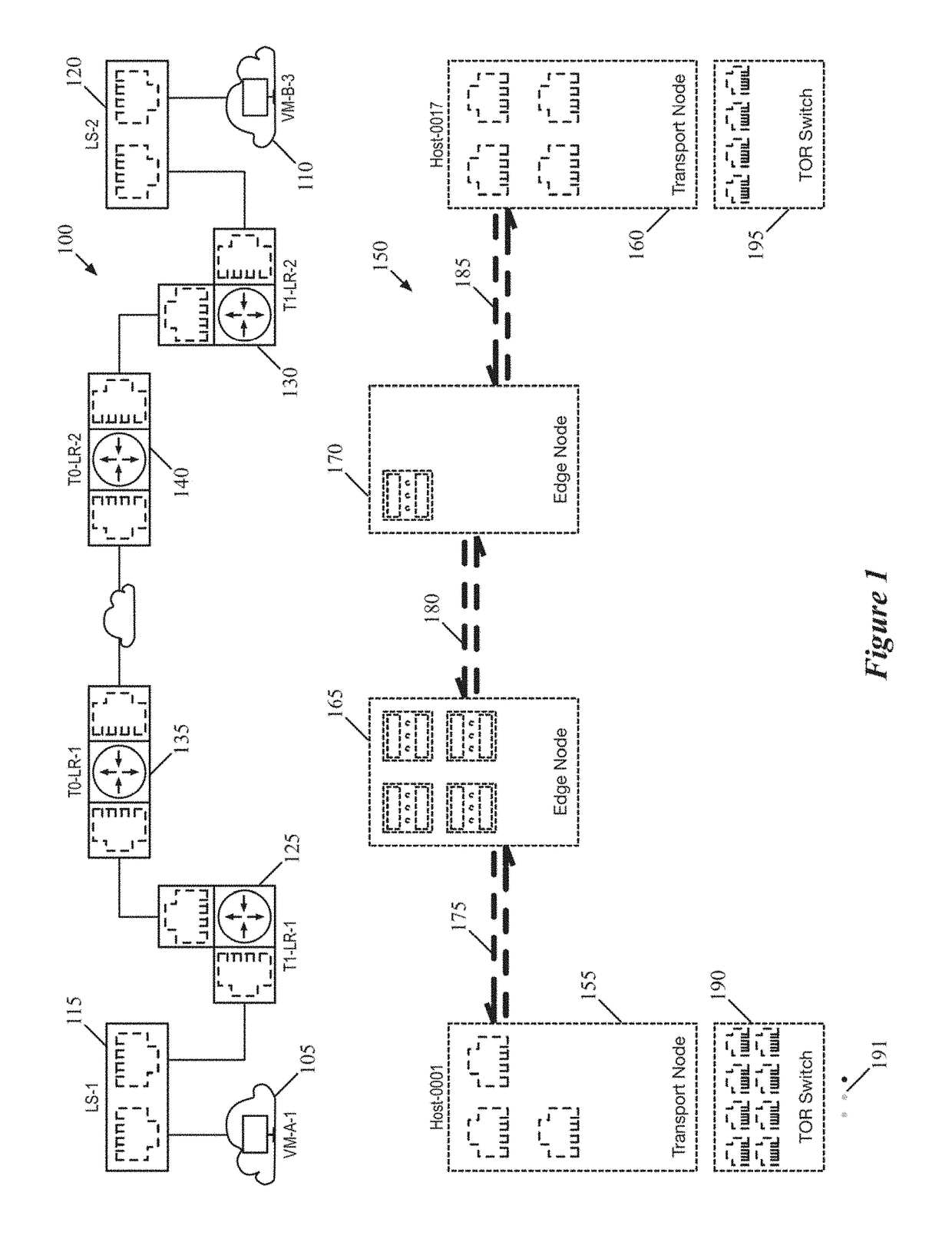
[0029]Some embodiments provide a visualization of a path between endpoints of a logical network that illustrates both the logical network components along the path as well as the physical network components that implement those logical network components for packets sent along the path. The visualization of some embodiments also aligns (e.g., vertically, horizontally, etc.) these physical and logical network components to illustrate the correspondence between the logical network components and the physical network components that implement them.

[0030]FIG. 1 illustrates an example of such a visualization, showi...


PUM


Abstract

Some embodiments provide a method that receives a request for information regarding a path between endpoints of a logical network. The method provides, for display, a visualization of the path including (i) a set of logical network components between the endpoints and (ii) a set of physical network components that implement the logical network components. The physical network components and the logical network components are aligned in the display. In some embodiments, the method receives data regarding a packet tracing operation between the endpoints. The method generates a display including (i) a visualization of the path between the endpoints of the logical network and (ii) a representation of the received data regarding the packet tracing operation, with the packet tracing operation data is visually linked to the components of the path.

Description

RELATED APPLICATIONS[0001]Benefit is claimed under 35 U.S.C. 119(a)-(d) to Foreign Application Serial No. 201741007938 filed in India entitled “VISUALIZATION OF PATH BETWEEN LOGICAL NETWORK ENDPOINTS”, on Mar. 7, 2017, by NICIRA, INC. which is herein incorporated in its entirety by reference for all purposes.[0002]The present application Ser. No. is related in subject matter to U.S. patent application Ser. No. 15 / 588,727, now published as U.S. Patent Publication 2018 / 0262594, which is incorporated herein by reference.BACKGROUND[0003]Network management applications that allow a user to configure and view logical networks in a datacenter (e.g., an enterprise datacenter, a multi-tenant datacenter, etc.) have traditionally provided users with a primarily text-based user interface. These applications enable users (e.g., network administrators) to view information about their networks via text information with, perhaps, simple image representations of basic components (e.g., simple raster...

Claims


Application Information

Patent Timeline
Patent Type & Authority Patents(United States)
IPC IPC(8): H04L12/931H04L12/823H04L12/26H04L12/939H04L29/08H04L47/32
CPCH04L49/20H04L43/10H04L49/555H04L47/32H04L69/323H04L41/22H04L43/045H04L67/75H04L41/40H04L41/0894H04L41/12H04L41/0893
Inventor NHU, ALEXANDERJEGARAJAN, BRIGHTON VINOSIK, JIAN SHENGOLLA, VENKATA RANGANATH BABUSONAWANE, SHIVRAJ SHAHAJIRAO
Owner NICIRA
Why Eureka
Try Eureka