Occupant protection system
a technology for occupant protection and head rest, which is applied in the direction of pedestrian/occupant safety arrangement, vehicular safety arrangment, vehicle components, etc., can solve the problems of difficult to stabilize the deployment behavior of the head rest airbag, and difficult to solve the interference between the upper deploying portion and the head, so as to achieve the stabilization effect of the deployment behavior of the second airbag
- Summary
- Abstract
- Description
- Claims
- Application Information
AI Technical Summary
Benefits of technology
Problems solved by technology
Method used
Image
Examples
first embodiment
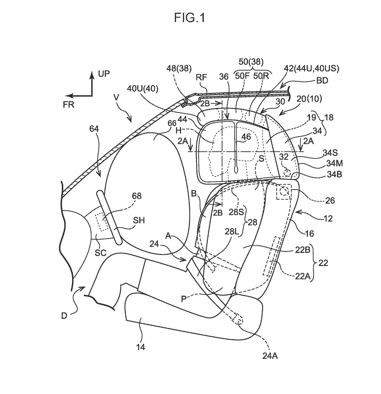
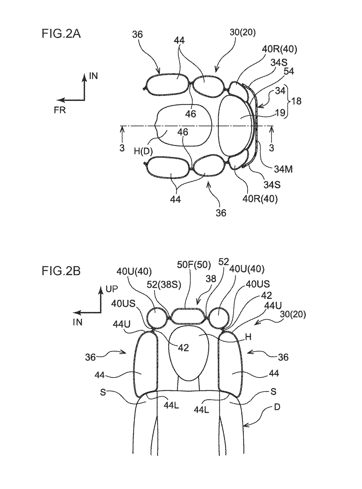
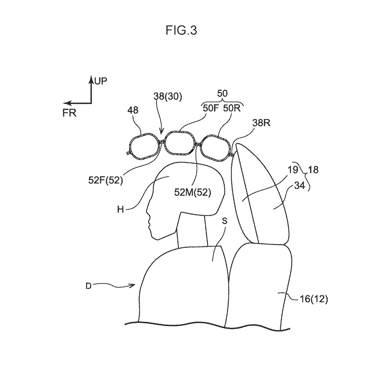
[0057]An occupant protection system 10 pertaining to a first embodiment will now be described on the basis of FIG. 1 to FIG. 7. It should be noted that arrow FR and arrow UP appropriately shown on the drawings indicate a forward direction (the direction that a seated occupant faces) and an upward direction of a vehicle seat 12, respectively. When description is given below simply using the directions of front / rear and upper / lower, unless otherwise specified these will be understood to mean front / rear in the vehicle forward and rearward direction and upper / lower in the vehicle vertical direction. It should also be noted that arrow IN appropriately shown in the drawings indicates a center side in the vehicle width direction of a vehicle V serving as a vehicle in which the vehicle seat 12 is installed.
[0058]{Configuration of Vehicle Seat in which Occupant Protection System is Installed}
[0059]As shown in FIG. 1 to FIG. 4B, the occupant protection system 10 is installed in the vehicle se...
example modifications
[0156
[0157]In the second embodiment, an example was described where the head protecting airbag 72 has the front deploying portion 80, but the present disclosure is not limited to this. For example, as shown in FIG. 13A, FIG. 13B, and FIG. 14, the head protecting airbag 72 may also be given a configuration pertaining to a third example modification that does not have the front deploying portion 80. In the third example modification, the space between the pair of front ducts 40F, that is, the front side of the upper deploying portion 38 in relation to the head H of the driver D, is open. In the configuration pertaining to the third example modification, basically the same effects can be obtained by the same operation as that of the first embodiment.
second embodiment
[0158]Furthermore, in the second embodiment, an example was described where the front deploying portion 80 interconnects, via the front ducts 40F, the pair of lateral inflating portions 44, but the present disclosure is not limited to this. For example, the head protecting airbag 72 may also be given a configuration where both vehicle width direction side edge portions 80S of the front deploying portion 80 are directly joined to the front edge portions 38F of the pair of lateral deploying portions 36 so that the front deploying portion 80 interconnects the front ends of the pair of lateral inflating portions 44.
[0159]Moreover, in the second embodiment, an example was described where the front deploying portion 80 includes a seeable structure, but the present disclosure is not limited to this. For example, the head protecting airbag 72 may also be given a configuration where, instead of the front deploying portion 80, it is equipped with a front deploying portion comprising a cloth t...
PUM
 Abstract
Description
Claims
Application Information
 - R&D
- Intellectual Property
- Life Sciences
- Materials
- Tech Scout
- Unparalleled Data Quality
- Higher Quality Content
- 60% Fewer Hallucinations
Browse by: Latest US Patents, China's latest patents, Technical Efficacy Thesaurus, Application Domain, Technology Topic, Popular Technical Reports.
© 2025 PatSnap. All rights reserved.Legal|Privacy policy|Modern Slavery Act Transparency Statement|Sitemap|About US| Contact US: help@patsnap.com


