Emergency vehicle control device

a technology for emergency vehicles and control devices, applied in control devices, external condition input parameters, tractors, etc., can solve the problems of difficult for a driver to continue driving, difficult to continue driving, etc., to achieve and easy and accurate estimation of the driver's state

Active Publication Date: 2019-05-14
HONDA MOTOR CO LTD
View PDF17 Cites 2 Cited by
  • Summary
  • Abstract
  • Description
  • Claims
  • Application Information

AI Technical Summary

Benefits of technology

[0007]The present disclosure has been made in consideration of such a problem, and provides an emergency vehicle control device capable of easily and accurately estimating a state that makes it difficult for the driver to continue driving and executing automatic vehicle stop control.

Problems solved by technology

An emergency situation which makes it difficult for a driver to continue driving, for instance, illness of the driver may suddenly occur in the vehicle.
In the former case, there is a possibility that the driver is in a state that makes it difficult to continue driving.
In the latter case, it is more probable than in the former case that the driver is in a state that makes it difficult to continue driving.
However, when the driver's physical condition gets worse, the driver may unconsciously depress the accelerator pedal and the brake pedal at the same time.

Method used


Image

  • Emergency vehicle control device
  • Emergency vehicle control device
  • Emergency vehicle control device

Examples


first embodiment

1. First Embodiment

[1-1. Configuration of Emergency Vehicle Control Device 10]

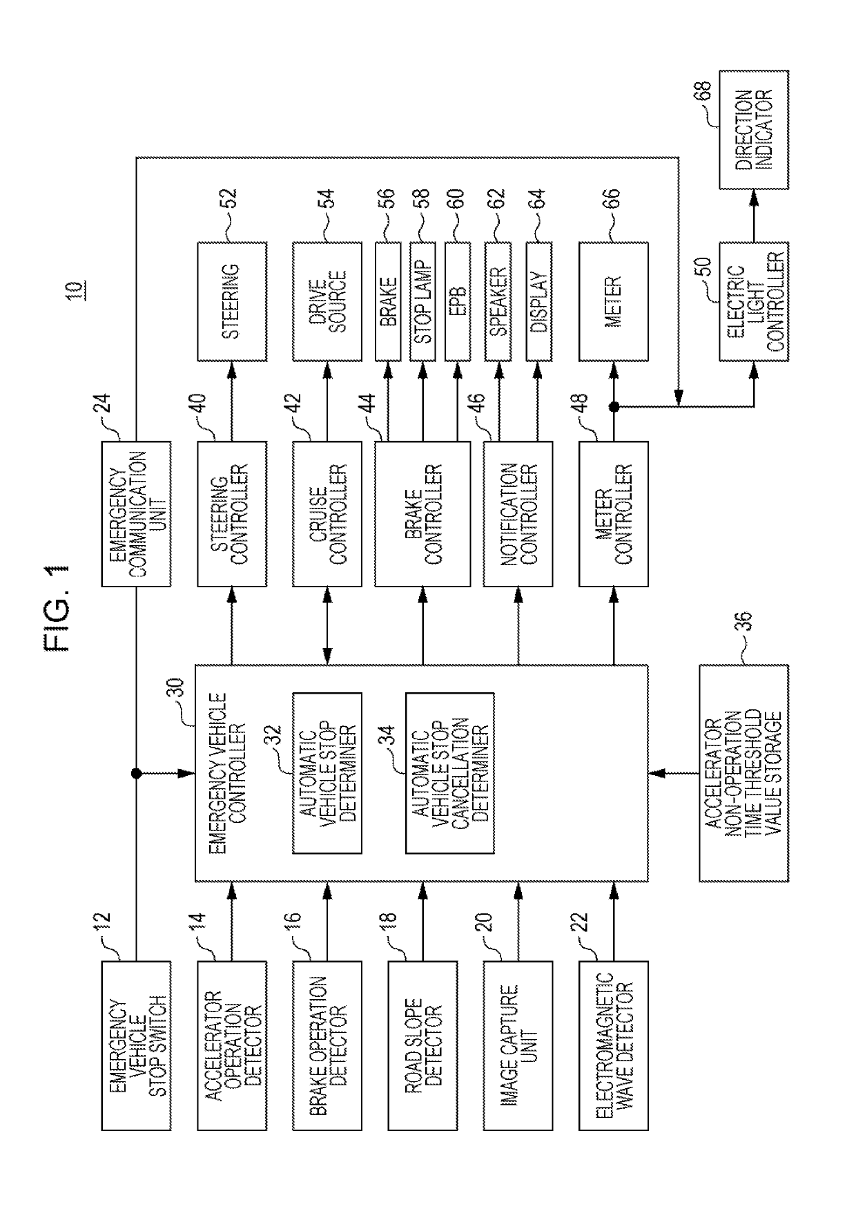
[0034]The configuration of the emergency vehicle control device 10 will be described with reference to FIG. 1. The emergency vehicle control device 10 has various information input units (12, 14, 16, 18, 20, 22), various controllers (30, 40, 42, 44, 46, 48, 50), and various controlled units (52, 54, 56, 58, 60, 62, 64, 66, 68). In addition, the emergency vehicle control device 10 has an emergency communication unit 24 that, makes an emergency call.

[1-1-1. Input Unit of Emergency Vehicle Control Device 10]

[0035]The emergency vehicle stop switch 12 is an automatic return switch (momentary switch) installed in a vehicle cabin. The type of the emergency vehicle stop switch 12 may be any type including a push type, a lever type, and a rotary type. The installation location of the emergency vehicle stop switch 12 may be any location in the vehicle cabin, but is preferably a location accessible by all occupants (...

example 4

ere Override is Performed During Execution of Automatic Vehicle Stop Control

[0106]The operational sequence during time t41 to t43 illustrated in FIG. 10 is the same as the operational sequence during time t31 to t33 illustrated in FIG. 9.

[0107]At time t44, the driver is assumed to perform the override by an accelerator operation. Then, the second deceleration control out of the vehicle control is suspended. On the other hand, the lane keeping control and the road departure mitigation control are continued. At this point, measurement of time with the accelerator operation time timer Tc starts. When no accelerator operation is performed at time t45 at which the accelerator operation time timer Tc is shorter than the accelerator operation time threshold value Tcth, the second deceleration control is resumed.

[0108]The operational sequence between time t46 and t47 is the same as the operational sequence between time t44 and t45.

[0109]The vehicle is stopped at time t48 as a result of the ...

example 5

ere Override is Performed During Execution of Automatic Vehicle Stop Control

[0110]The operational sequence during time t51 to t53 illustrated in FIG. 11 is the same as the operational sequence during time t31 to t33 illustrated, in FIG. 3 and the operational sequence during time t41 to t43 illustrated in FIG. 10.

[0111]At time t54, the driver is assumed to perform the override by an accelerator operation. Then, the second deceleration control out of the vehicle control is suspended. On the other hand, the lane keeping control and the road departure mitigation control are continued. At this point, measurement of time with the accelerator operation time timer Tc starts. At time t55 at which the accelerator operation time timer Tc reaches the accelerator operation time threshold value timer Tcth, execution of the automatic vehicle stop control is cancelled. At time t56 at which no accelerator operation is performed, the operational sequence returns to the stand-by state and normal drivi...


PUM


Abstract

An emergency vehicle control device includes an emergency vehicle stop switch (emergency situation detector) that detects or estimates an emergency situation; and an accelerator operation detector that detects whether or not an accelerator is being operated. When an emergency situation is detected or estimated by the emergency situation detector and an accelerator non-operation state lasting for an accelerator non-operation time threshold value or longer is detected by the accelerator operation detector while the vehicle is running, the vehicle is automatically stopped regardless of whether or not a steering operation is performed.

Description

CROSS REFERENCES TO RELATED APPLICATIONS[0001]The present application claims priority under 35 U.S.C. $119 to Japanese Patent Application No. 2015-138999, filed Jul. 10, 2015, entitled “Emergency Vehicle Control Device.” The contents of this application are incorporated herein by reference in their entirety.BACKGROUND[0002]1. Field[0003]The present disclosure relates to an emergency vehicle control device that automatically stop a vehicle when an emergency situation occurs which makes it difficult for a driver to continue driving while the vehicle is running.[0004]2. Description of the Related Art[0005]An emergency situation which makes it difficult for a driver to continue driving, for instance, illness of the driver may suddenly occur in the vehicle. To cope with such a situation, devices have been developed that, when it is difficult for the driver to continue driving, stops the vehicle automatically. In such devices, accidental activation of automatic vehicle stop control has to...

Claims


Application Information

Patent Timeline
Patent Type & Authority Patents(United States)
IPC IPC(8): B60W30/18B60K28/06B60W40/08
CPCB60W30/18109B60K28/06B60W2040/0818B60W2720/106B60W2540/12B60W2540/18B60W2550/142B60W2540/10B60W2552/15
Inventor NAKATSUKA, MASAYUKIOSHIDA, KEIKATAYAMA, MAKOTOKURAHASHI, YUKINORI
Owner HONDA MOTOR CO LTD
Why Eureka
Try Eureka