Emergency vehicle control device

a technology for emergency vehicles and control devices, applied in the direction of electrical control, process and machine control, etc., can solve the problems of difficult for a driver to continue driving and difficult to continue driving, and achieve the effect of accurately and easily estimating the driver's sta

Active Publication Date: 2017-01-12
HONDA MOTOR CO LTD
View PDF6 Cites 2 Cited by
  • Summary
  • Abstract
  • Description
  • Claims
  • Application Information

AI Technical Summary

Benefits of technology

[0012]According to the present disclosure, it is possible to easily and accurately estimate the driver's state that makes it difficult to continue driving and to execute automatic vehicle stop control.

Problems solved by technology

An emergency situation which makes it difficult for a driver to continue driving, for instance, illness of the driver may suddenly occur in the vehicle.
Also, even when vehicle speed maintaining control or inter-vehicle distance maintaining control is performed, it is possible to estimate the driver's state making it difficult to continue driving based on whether or not an accelerator operation is performed.

Method used


Image

  • Emergency vehicle control device
  • Emergency vehicle control device
  • Emergency vehicle control device

Examples


first embodiment

1. First Embodiment

1-1. Configuration of Emergency Vehicle Control Device 10

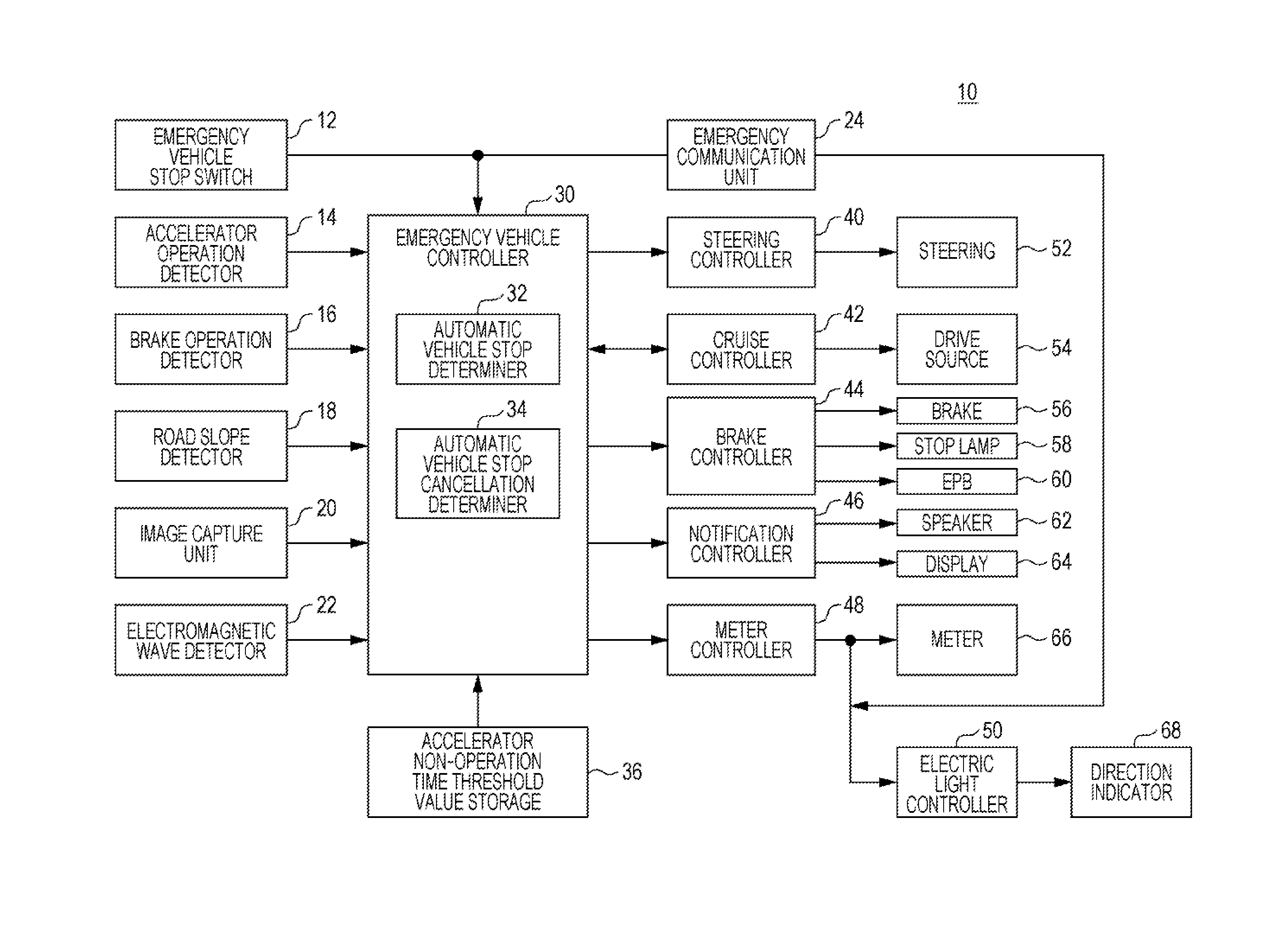
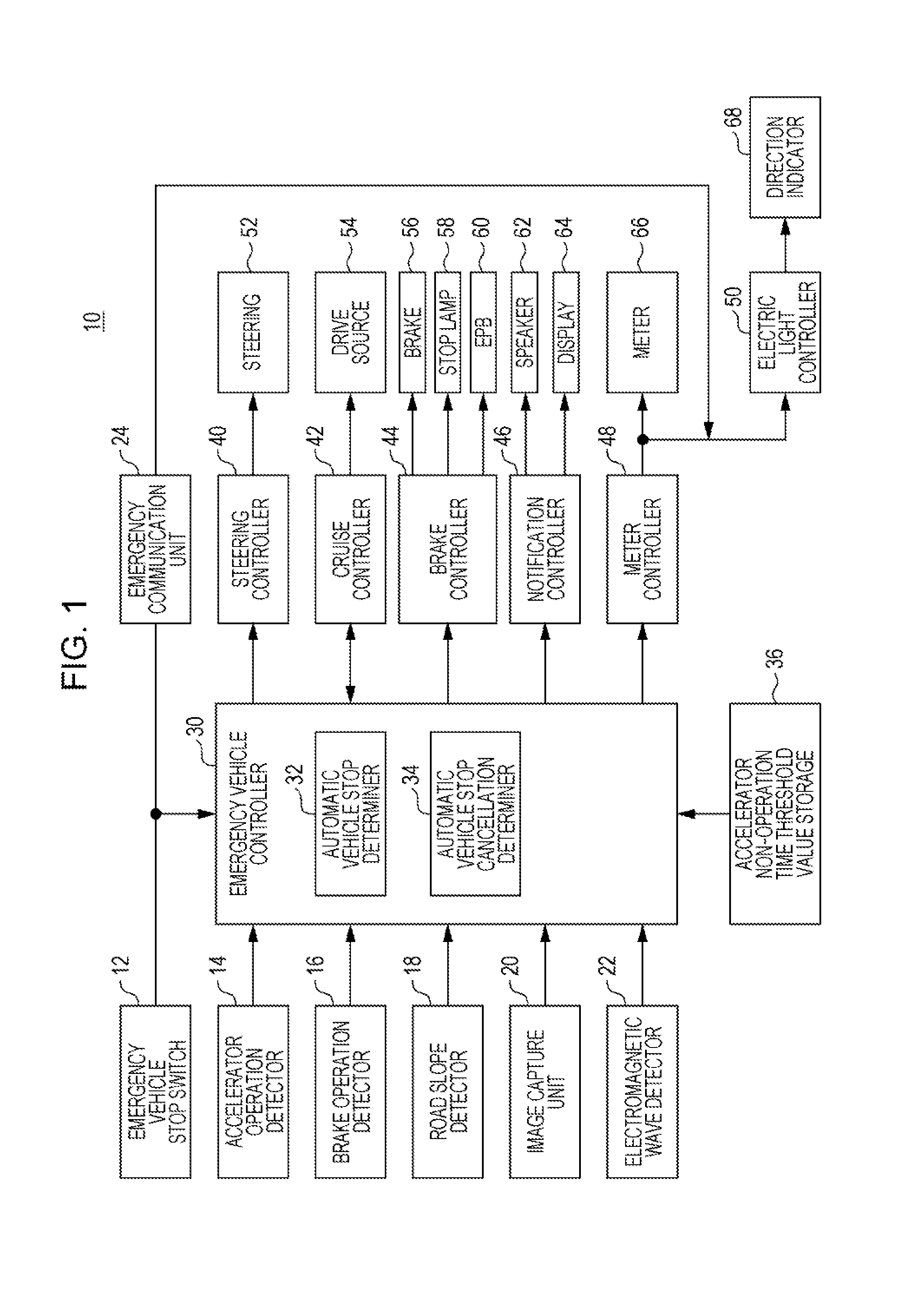
[0027]The configuration of the emergency vehicle control device 10 will be described with reference to FIG. 1. The emergency vehicle control device 10 has various information input units (12, 14, 16, 18, 20, 22), various controllers (30, 40, 42, 44, 46, 48, 50), and various controlled units (52, 54, 56, 58, 60, 62, 64, 66, 68). In addition, the emergency vehicle control device 10 has an emergency communication unit 24 that makes an emergency call.

1-1-1. Input Unit of Emergency Vehicle Control Device 10

[0028]The emergency vehicle stop switch 12 is an automatic return switch (momentary switch) installed in a vehicle cabin. The type of the emergency vehicle stop switch 12 may be any type including a push type, a lever type, and a rotary type. The installation location of the emergency vehicle stop switch 12 may be any location in the vehicle cabin, but is preferably a location accessible by all occupants (the d...

example 1

Case where Difficulty of Continuous Driving is Determined before Operation of Emergency Vehicle Stop Switch 12

[0091]As illustrated in FIG. 7, it is assumed that an accelerator operation is performed by the driver in the stand-by state until time t11. When the driver stops the accelerator operation at time t11 and no accelerator operation is performed, measurement of time with the accelerator non-operation time timer Tn starts. During this period, there is a possibility that the driver is in a state that makes it difficult to continue driving.

[0092]It is assumed that an occupant determines that the driver is in a state that makes it difficult to continue driving and operates the emergency vehicle stop switch 12 (SW) starting from time t12 at which the accelerator non-operation time timer Tn is greater than or equal to the accelerator non-operation time threshold value Tnth1 until time t13. At this point, the driver's state making it difficult to continue driving is determined, and th...

example 2

Case 1 where Difficulty of Continuous Driving is Determined after Operation of Emergency Vehicle Stop Switch 12

[0094]The operational sequence illustrated in FIG. 8 is executed by a vehicle in which ACC / CC is in operation. It is assumed that an occupant determines that the driver is in a state that makes it difficult to continue driving and operates the emergency vehicle stop switch 12 (SW) starting from time t21 in the stand-by state until time t22. At this point, it is probable that the driver is in a state that makes it difficult to continue driving.

[0095]At time t22, measurement of time with the accelerator non-operation time timer Tn starts. At this point, OFF operation of ACC / CC, the first deceleration control, the lane keeping control, and the road departure mitigation control are executed. In response to an operation of the emergency vehicle stop switch 12 (SW), the emergency communication unit 24 establishes a communication line to an emergency lifesaving center. Thus, phone...


PUM


Abstract

An emergency vehicle control device includes an emergency vehicle stop switch that detects or estimates an emergency situation; an accelerator operation detector that detects whether or not an accelerator is being operated; and a cruise controller that executes vehicle speed maintaining control or inter-vehicle distance maintaining control for a preceding vehicle. In the case where an emergency situation is detected or estimated by the emergency vehicle stop switch while a vehicle is running, execution of control by the cruise controller is prohibited, and when an accelerator non-operation state lasting for an accelerator non-operation time threshold value or longer since the prohibition of the control is detected by the accelerator operation detector, the vehicle is automatically stopped.

Description

CROSS REFERENCES TO RELATED APPLICATIONS[0001]The present application claims priority under 35 U.S.C. §119 to Japanese Patent Application No. 2015-139001, filed Jul. 10, 2015, entitled “Emergency Vehicle Control Device.” The contents of this application are incorporated herein by reference in their entirety.BACKGROUND[0002]1. Field[0003]The present disclosure relates to an emergency vehicle control device that automatically stop a vehicle when an emergency situation occurs which makes it difficult for a driver to continue driving while the vehicle is running.[0004]2. Description of the Related Art[0005]An emergency situation which makes it difficult for a driver to continue driving, for instance, illness of the driver may suddenly occur in the vehicle. To cope with such a situation, devices have been developed that, when it is difficult for the driver to continue driving, stops the vehicle automatically. In such devices, accidental activation of automatic vehicle stop control has to...

Claims


Application Information

Patent Timeline
Patent Type & Authority Applications(United States)
IPC IPC(8): F02D41/22B60K31/00B60W30/12F02D41/12B62D6/04
CPCF02D41/22F02D41/12B60K31/00B60W30/12B62D6/04B60K28/06B60T7/14B60W2540/26B60W2540/10B60W2720/106
Inventor NAKATSUKA, MASAYUKIOSHIDA, KEIKATAYAMA, MAKOTOKURAHASHI, YUKINORI
Owner HONDA MOTOR CO LTD
Why Eureka
Try Eureka