Estimating device and estimating system

a technology of estimating device and estimating system, which is applied in the direction of electrical programme control, program control, instruments, etc., can solve the problems of inability to remove the above-mentioned remaining portion and inability to trial and error, and achieve the effect of accurately and easily estimating the position of the rotary axis

Active Publication Date: 2022-05-24
FANUC LTD
View PDF4 Cites 0 Cited by
  • Summary
  • Abstract
  • Description
  • Claims
  • Application Information

AI Technical Summary

Benefits of technology

[0006]Thus, the present invention has the object of providing an estimating device and an estimating system in which it is possible to easily and accurately estimate the position of the rotary axis of a machined object that is subjected to a lathe turning process.
[0009]According to the present invention, the estimating device and the estimating system are provided, in which it is possible to easily and accurately estimate the position of the rotary axis of a workpiece that is subjected to a lathe turning process.

Problems solved by technology

In this instance, the aforementioned remaining portion cannot be removed if the tool is deviated even slightly from the position of the rotating shaft.
However, such a trial and error technique is not preferable since it depends significantly on the skill of the operator.

Method used


Image

  • Estimating device and estimating system
  • Estimating device and estimating system
  • Estimating device and estimating system

Examples


first embodiment

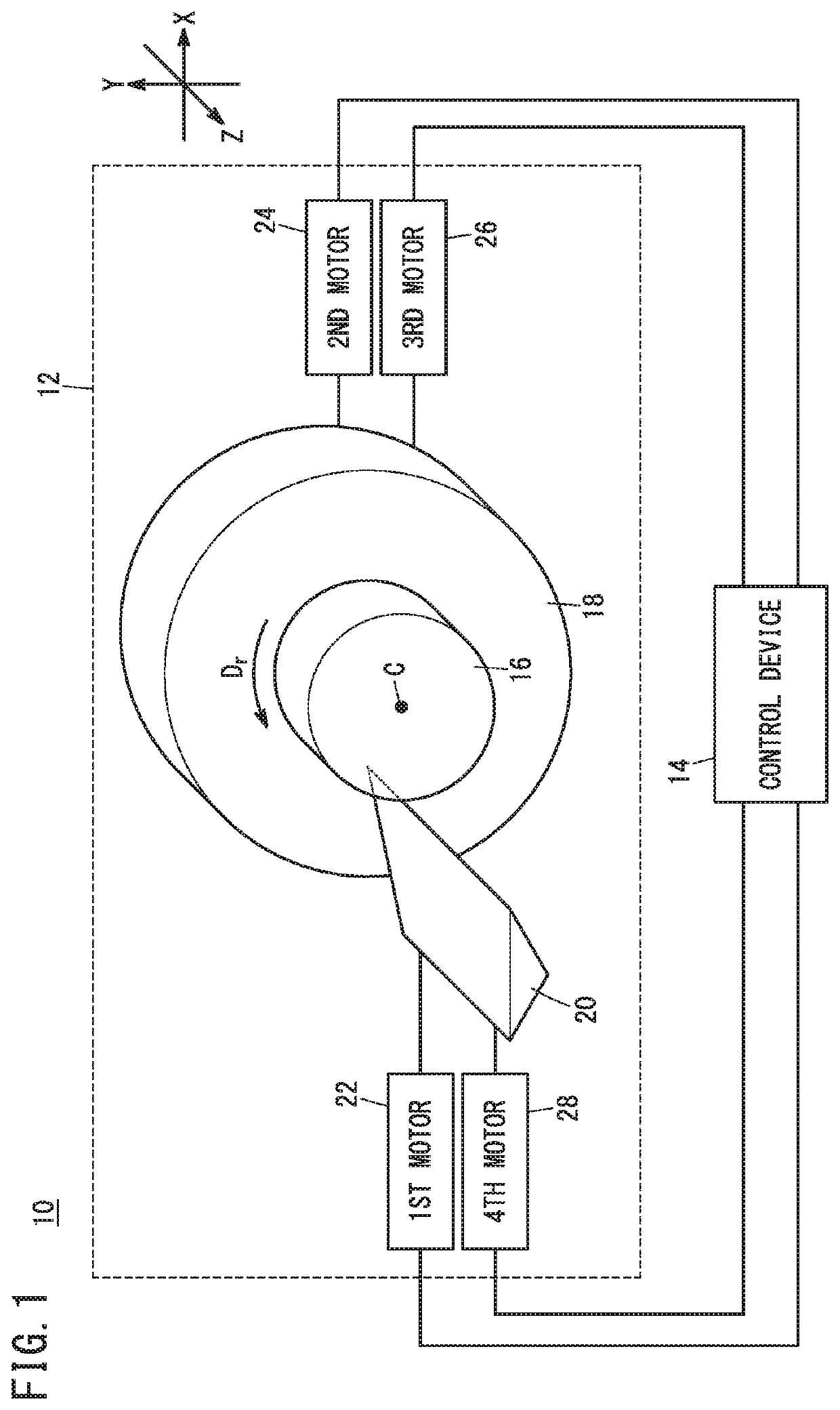
[0024]FIG. 1 is a schematic configuration diagram of a machine tool 10 according to a first embodiment. In the present embodiment, a first direction (X-axis direction), a second direction (Y-axis direction), and a third direction (Z-axis direction) are directions that are perpendicular to each other.

[0025]The machine tool 10 according to the present embodiment is equipped with a processing machine 12 and a control device 14. The processing machine 12 is a machine that subjects a machined object (workpiece or object to be machined) 16 to a turning process (lathe turning process). The machined object 16 is not of a configuration of being possessed by the processing machine 12 (see FIG. 1).

[0026]The processing machine 12 of the present embodiment, although not limited thereto, is also referred to as a precision processing machine, which serves to machine the machined object 16 according to a command with a machining accuracy of less than or equal to 100 nm (nanometers). The estimating ...

modification 1

(Modification 1)

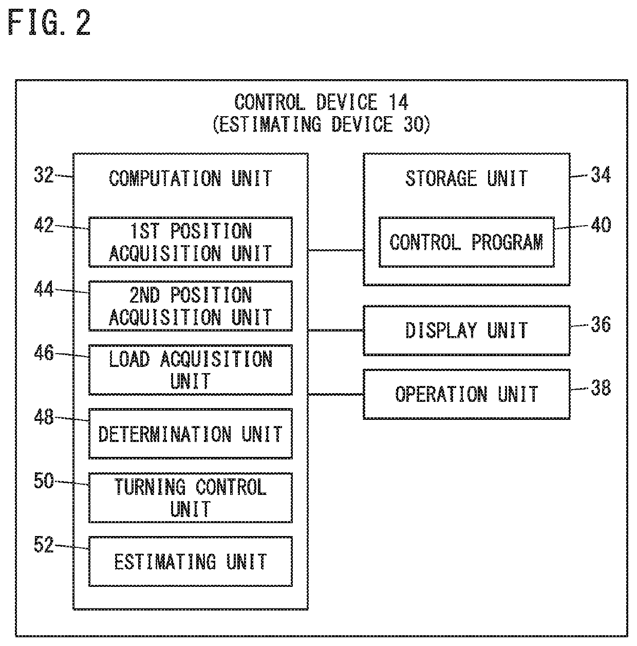
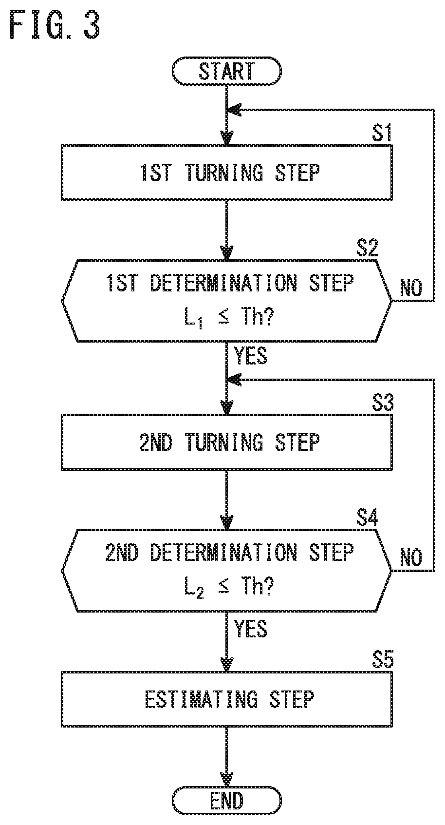
[0081]The estimating unit 52 may select, as the first directional position Px, an average value of the first directional position of the tool 20 at a time when a first load has become less than or equal to a threshold value Th, and the first directional position of the tool 20 at a time when a second load has become less than or equal to a threshold value Th.

[0082]In this instance, the first load is a first directional load based on the fluctuation range of deviation of the position acquired by the first position acquisition unit 42 from the position indicated by the first command. Further, the second load is a first directional load based on the drive current or the torque of the first motor 22. The first load and the second load can be acquired by the load acquisition unit 46.

[0083]Further, the estimating unit 52 may select, as the second directional position Py, an average value of the second directional position of the tool 20 at a time when a third load has beco...

modification 2

(Modification 2)

[0086]FIG. 8 is a schematic configuration diagram of the estimating device 30 according to a second modification.

[0087]The estimating device 30 (the control device 14 in which the estimating device 30 is provided) may be further equipped with a compensation unit 54. The compensation unit 54 compensates the first directional position Px based on the first directional load L1, and compensates the second directional position Py based on the second directional load L2.

[0088]The tool 20 that undergoes relative movement with respect to the machined object 16 while performing cutting receives a repulsive force from the machined object 16. Accordingly, there is a concern that, from an extremely detailed point of view, the first directional position Px and the second directional position Py selected by the estimating unit 52 may deviate respectively from the actual position of the rotary axis C in the first direction and the actual position of the rotary axis C in the second ...


PUM


Abstract

An estimating device estimating a rotary axis position of a workpiece includes first and second position acquisition units acquiring tool positions in first and second directions, a load acquisition unit acquiring first and second directional loads of the tool in the first and second directions, a determination unit determining whether or not the first and second directional loads each are a threshold or less, a turning control unit performing a lathe turning on the workpiece until the first directional load becomes the threshold or less and thereafter performing a lathe turning thereon until the second directional load becomes the threshold or less, and an estimating unit estimating the rotary axis position based on a first directional position of the tool when the first directional load has become the threshold or less, and a second directional position thereof when the second directional load has become the threshold or less.

Description

CROSS-REFERENCE TO RELATED APPLICATION[0001]This application is based upon and claims the benefit of priority from Japanese Patent Application No. 2019-203365 filed on Nov. 8, 2019, the contents of which are incorporated herein by reference.BACKGROUND OF THE INVENTIONField of the Invention[0002]The present invention relates to an estimating device and an estimating system configured to estimate the position of a rotary axis of a machined object that is subjected to a lathe turning process.Description of the Related Art[0003]Japanese Laid-Open Patent Publication No. 2003-195917 discloses an example of a machine tool that performs a turning (lathing) process. The turning process is a machining process performed in a state in which a machined object is rotated. As disclosed therein, the turning process is performed by causing a workpiece (machined object) to be rotated about a C-axis (rotary axis).SUMMARY OF THE INVENTION[0004]In the turning process, a portion corresponding to a center...

Claims


Application Information

Patent Timeline
Patent Type & Authority Patents(United States)
IPC IPC(8): B23Q15/12B23Q15/14G05B19/404B23Q17/09B23Q17/22
CPCB23Q17/0961B23Q15/12B23Q15/14B23Q17/2233G05B19/404B23Q2717/003G05B19/19G05B2219/35349B23B25/06G05B2219/49177G05B2219/45248
Inventor SHIMIZU, TOMOKI
Owner FANUC LTD
Why Eureka
Try Eureka