Far electromagnetic field estimation method and apparatus, and near electromagnetic field measurement apparatus

a technology of electromagnetic field and estimation method, applied in the direction of instruments, measurement devices, electromagentic field characteristics, etc., can solve the problems of increasing the total investment, maintenance and operation costs of the building, the maintenance and operation costs of the building, the equipment, etc., and achieve the effect of easy and accurate estimation of the electromagnetic field

Active Publication Date: 2016-05-10
TDK CORPARATION
View PDF18 Cites 2 Cited by
  • Summary
  • Abstract
  • Description
  • Claims
  • Application Information

AI Technical Summary

Benefits of technology

[0012]It is a first object of the present invention to provide a far electromagnetic field estimation method and apparatus that can easily and accurately estimate an electromagnetic field at a virtual observation point distant from a radiation source of an electromagnetic wave on the basis of an electromagnetic field measured near the radiation source under the condition that there is a ground plane.
[0031]According to the far electromagnetic field estimation method and apparatus of the present invention, a plurality of measurement points are set on a measurement surface, and either a plurality of measurement-point electric fields or a plurality of measurement-point magnetic fields, or both, are measured. In addition, a plurality of mirror image measurement points are set on a mirror image measurement surface, and either a plurality of mirror image measurement-point electric fields or a plurality of mirror image measurement-point magnetic fields, or both, are calculated on the basis of the plurality of measurement-point electric fields and / or the plurality of measurement-point magnetic fields measured. At least either one of an electric field and a magnetic field that are estimated to be formed at the virtual observation point is then calculated on the basis of the plurality of measurement-point electric fields and / or the plurality of measurement-point magnetic fields measured and the plurality of mirror image measurement-point electric fields and / or the plurality of mirror image measurement-point magnetic fields calculated. The present invention thereby makes it possible that an electromagnetic field at a virtual observation point distant from a radiation source of electromagnetic waves can be easily and accurately estimated on the basis of an electromagnetic field measured near the radiation source under the condition that there is a ground plane.
[0032]Further, the near electromagnetic field measurement apparatus of the present invention makes it possible to measure either the plurality of measurement-point electric fields or the plurality of measurement-point magnetic fields, or both, which are needed to implement the far electromagnetic field estimation method of the present invention.

Problems solved by technology

Disadvantageously, radio anechoic chambers need a relatively large length, width and height as described above, need a large-scale building and facility, and increase the total investment and the maintenance and operation costs for the building, facility, and various necessary equipment.
Thus, the method does not take account of the effect of a ground plane.
In actuality, however, it is difficult to float the object to be measured in the air, and therefore the near electromagnetic field at the surface under the object to be measured is difficult to measure.
Such a method is thus difficult to apply to a test for measuring radiated emissions.
This causes the problem that a lot of calculation processing time is needed.

Method used


Image

  • Far electromagnetic field estimation method and apparatus, and near electromagnetic field measurement apparatus
  • Far electromagnetic field estimation method and apparatus, and near electromagnetic field measurement apparatus
  • Far electromagnetic field estimation method and apparatus, and near electromagnetic field measurement apparatus

Examples


first embodiment

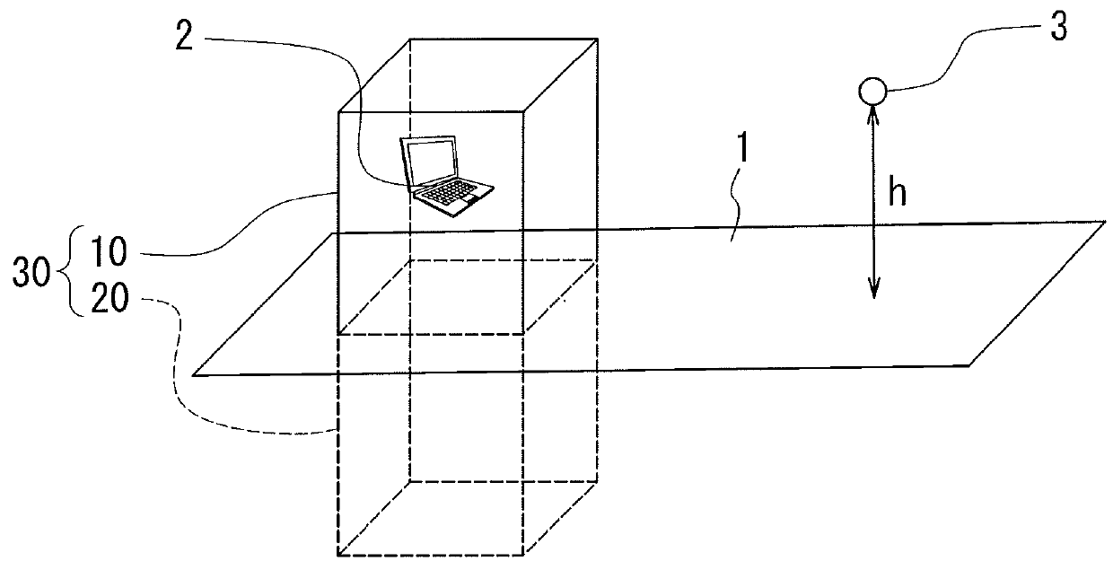
[0077]Preferred embodiments of the present invention will now be described in detail with reference to the drawings. First, reference is made to FIG. 1 to describe an overview of a far electromagnetic field estimation method according to a first embodiment of the invention.

[0078]As shown in FIG. 1, the far electromagnetic field estimation method according to the first embodiment is a method for determining at least either one of an electric field and a magnetic field that are estimated to be formed at a virtual observation point 3 distant from a radiation source 2 of electromagnetic waves under the condition that the radiation source 2 is located in either one of two spaces sectioned by a ground plane 1. The far electromagnetic field estimation method according to the first embodiment is used, for example, for a test for measuring radiated emissions radiated from the radiation source 2 according to the EMC standards.

[0079]The ground plane 1 is an isopotential plane. For example, the...

verification experiment

[Verification Experiment]

[0109]An experiment was performed to verify the validity of the far electromagnetic field estimation method according to the first embodiment. The experiment will now be described with reference to FIG. 6 to FIG. 17 and FIG. 18A to FIG. 25C. The experiment was separately performed for a case where the electromagnetic waves radiated from the radiation source 2 were horizontally polarized ones (hereinafter referred to as the case of horizontally polarized waves) and for a case where the electromagnetic waves radiated from the radiation source 2 were vertically polarized ones (hereinafter referred to as the case of vertically polarized waves).

[0110]FIG. 6 is an explanatory diagram for explaining the experiment method for the case of horizontally polarized waves. In the experiment, a biconical antenna 31 was used as the radiation source 2. For the case of horizontally polarized waves, as shown in FIG. 6, the biconical antenna 31 was positioned at a height of 1 m...

second embodiment

[0201]A second embodiment of the invention will now be described. FIG. 36 is an explanatory diagram for explaining an overview of a far electromagnetic field estimation method according to the second embodiment. As shown in FIG. 36, the second embodiment differs from the first embodiment in the shape of the measurement surface 10. More specifically, the measurement surface 10 of the second embodiment is constituted by a cylindrical surface and a circular surface that closes an opening present at one axial end of the cylindrical surface. The measurement surface 10 is arranged in such an orientation that an opening present at the other axial end of the cylindrical surface is closed by the ground plane 1. As a result, the measurement surface 10 forms a closed surface in combination with the ground plane 1. The measurement surface 10 and the mirror image measurement surface 20, in combination, form a closed surface 30. The closed surface 30 has a shape formed by a cylindrical surface an...


PUM


Abstract

A far electromagnetic field estimation method includes assuming a measurement surface, setting a plurality of measurement points on the measurement surface, and measuring electromagnetic fields at the plurality of measurement points. The measurement surface in combination with a ground plane forms a closed surface surrounding a radiation source. A virtual observation point is outside a space formed inside the closed surface. Further, electromagnetic fields at a plurality of mirror image measurement points on a mirror image measurement surface having a plane-symmetrical relationship with the measurement surface are calculated on the basis of the electromagnetic fields at the plurality of measurement points. Then, a far electromagnetic field at the virtual observation point is estimated on the basis of the electromagnetic fields at the plurality of measurement points and at the plurality of mirror image measurement points.

Description

BACKGROUND OF THE INVENTION[0001]1. Field of the Invention[0002]The present invention relates to a far electromagnetic field estimation method and apparatus for measuring an electromagnetic field generated by a radiation source of electromagnetic waves, such as an electronic apparatus, near the radiation source and estimating, on the basis of the measured electromagnetic field, an electromagnetic field at a virtual observation point located farther from the radiation source, and to a near electromagnetic field measurement apparatus suited for implementing the far electromagnetic field estimation method.[0003]2. Description of the Related Art[0004]A test for measuring radiated emissions radiated from an electronic apparatus or the like is typically performed according to an internationally-defined test condition and test method, mostly by measuring the radiated emissions at a distance of 10 m or 3 m from the radiation source of the radiated emissions. A test for measuring radiated em...

Claims


Application Information

Patent Timeline
Patent Type & Authority Patents(United States)
IPC IPC(8): G01R29/08
CPCG01R29/0871G01R29/0821G01R29/0892
Inventor KURIHARA, HIROSHIMIDORI, MASATAKATORII, MASASHI
Owner TDK CORPARATION
Why Eureka
Try Eureka