Eureka AIR delivers breakthrough ideas for toughest innovation challenges, trusted by R&D personnel around the world.

Reconfigurable motion generator

a generator and reconfigurable technology, applied in the field of mechanical devices, can solve the problems of limited use of reconfigurable motion generators, and achieve the effects of synthesis task, precise and rapid motion, and low cos

Active Publication Date: 2019-05-28
SOUTH DAKOTA SCHOOL OF MINES AND TECHNOLOGY
View PDF6 Cites 0 Cited by
  • Summary
  • Abstract
  • Description
  • Claims
  • Application Information

AI Technical Summary

Benefits of technology

[0010]Reconfigurable motion generators are a new class of mechanical devices that use only one actuator to achieve complex multi-phase motions of the end-effector attached to the coupler. The reconfigurable motion generator mechanism of the invention may replace the current complex and expensive serial chain robots and offers a cheap and robust design that can be used, for example and not by way of limitation, in pick-and-place operations in industry. The following applications are some of the applications that can benefit from the extremely precise and rapid motions that can be achieved by reconfigurable motion generators, and are presented here as exemplary of the many applications that can benefit from the use of reconfigurable motion generators: 1) pick-and-place operations involving high speed and low loads; 2) welding, machining and polishing operations; 3) robotic manipulation, vision and inspection; and 4) production and assembly of families of products that have slight changes in geometry and dimensions.
[0011]Reconfigurable motion generators are not without limitations. Reconfigurable motion generators may be designed based on specific geometries and needs of the anticipated application and the rigid body motion task that is desired by the user, which may involve dimensional synthesis of the parameters for a reconfigurable motion generator of the invention to be utilized for a specific application. This synthesis task, however, may be simplified and made easier by the implementation of Computer Aided Design (CAD) and synthesis software that may allow faster and more efficient design of an application-specific reconfigurable motion generator.

Problems solved by technology

Reconfigurable motion generators may also limited by the wired connections to the brakes which limit the rotation of the input link.

Method used


Image

  • Reconfigurable motion generator
  • Reconfigurable motion generator
  • Reconfigurable motion generator

Examples


example 1

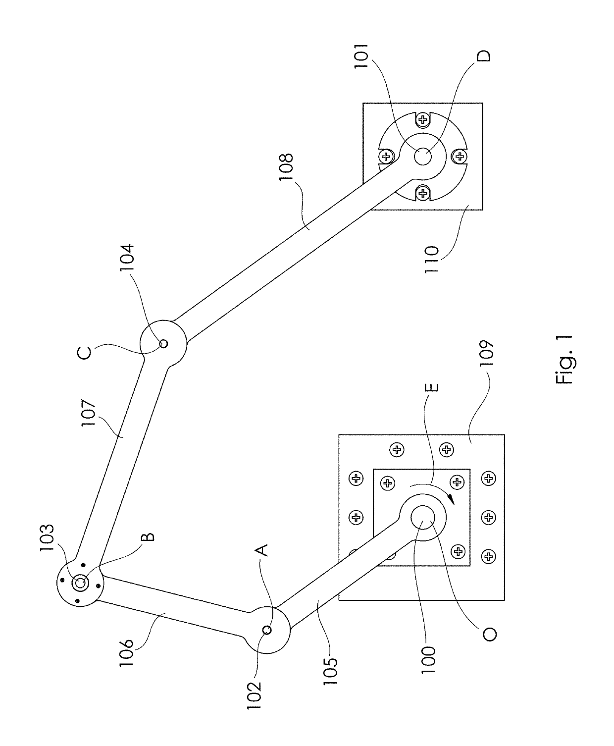
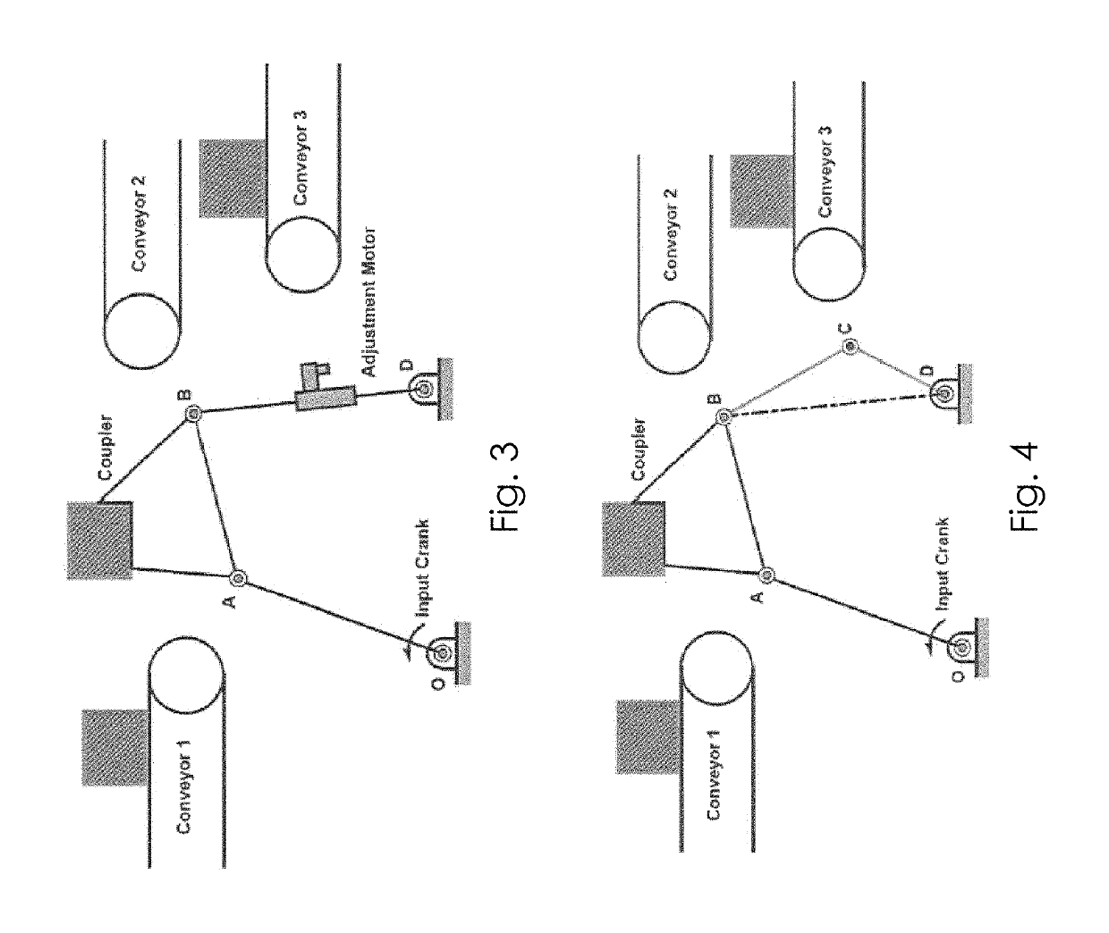
[0071]An embodiment of a reconfigurable motion generator of the present invention as shown in FIG. 8. In this configuration revolute joint A is locked and link OB becomes the input link of the reconfigurable motion generator of the present invention. Thus, the original two degree of freedom five-bar mechanism is transformed into a one degree of freedom four-bar mechanism OBCD in which the input, output, coupler, and fixed links are OB, CD, BC, and OD respectively. The length of the input link OB may be changed by controlling the position at which joint A is locked by operation of a brake or clutch. This facilitates control over the length of the input link OB depending on the range of OAB. This parameter adjustment can be realized by means of a clutch or brake at joint A.

example 2

[0072]A yet further embodiment of a reconfigurable motion generator of the present invention as shown in FIG. 9. In this configuration joint B is locked and link AC becomes the coupler link of the reconfigurable motion generator of the present invention. Thus, the original two degree of freedom five-bar mechanism is transformed into a one degree of freedom four-bar mechanism OACD in which the input, output, coupler, and fixed links are OA, CD, AC, and OD respectively. The length of the coupler link AC may be changed by controlling the position at which joint B is locked by operation of a brake or clutch. This facilitates control over the length of the coupler link AC depending on the range of ABC.

example 3

[0073]A yet further embodiment of a reconfigurable motion generator of the present invention as shown in FIG. 10. In this configuration joint C is locked and link BD becomes the output link of the reconfigurable motion generator of the present invention. Thus, the original two degree of freedom five-bar mechanism is transformed into a one degree of freedom four-bar mechanism OABD in which the input, output, coupler, and fixed links are OA, BD, AB, and OD respectively. The length of the output link BD may be changed by controlling the position at which joint C is locked by operation of a brake or clutch. This facilitates control over the length of the output link BD depending on the range of BCD.


PUM


Abstract

A reconfigurable motion generator and control system for multi-phase motion generation. Reconfigurable motion generators are a new class of mechanical devices that are designed for a specific part family and their associated motion generation tasks. The reconfigurable motion generator may utilize revolute joints for link length and pivot adjustment to achieve different configurations from the same set of links. Due to the nature of adjustment of the mechanism this methodology may be used for different types of motion generation tasks such as (a) common start position, (b) common end position, (c) common intermediate position, and (d) distinct motion generation tasks with no common positions. This technique can be applied towards the synthesis of reconfigurable motion generators for use in many planar or spherical applications involving multi-phase function, path, and motion generation tasks.

Description

CROSS REFERENCE TO RELATED APPLICATIONS[0001]This non-provisional application for patent filed in the United States Patent and Trademark Office (USPTO) under 35 U.S.C. § 111(a) claims the benefit of provisional application Ser. No. 61 / 987,153, which was filed in the USPTO on May 1, 2014, and which is incorporated herein in its entirety by reference.STATEMENT REGARDING FEDERALLY SPONSORED RESEARCH OR DEVELOPMENT[0002]Not applicable.INCORPORATION-BY-REFERENCE OF MATERIAL SUBMITTED ON A COMPACT DISK[0003]Not applicable.FIELD OF INVENTION[0004]This invention relates to the field of mechanical devices. Specifically the invention relates to Reconfigurable Motion Generators (RMGs) for multi-phase motion generation. Reconfigurable Motion Generators are a new class of mechanical devices that are designed for a specific part family and their associated motion generation tasks.BACKGROUND OF THE INVENTION[0005]Reconfigurable Motion Generators are capable of configuration changes according to va...

Claims


Application Information

Patent Timeline
Patent Type & Authority Patents(United States)
IPC IPC(8): B25J9/00F16H21/40F16H21/52G05G21/00B25J9/10
CPCF16H21/52B25J9/106G05G21/00F16H21/40Y10T74/18232
Inventor LAROCHELLE, PIERREVENKATARAMANUJAM, VENKATESH
Owner SOUTH DAKOTA SCHOOL OF MINES AND TECHNOLOGY
Why Eureka
Eureka Blog
Learn More