[0004]It is an object of the invention to provide a cutting member of a saw chain which is also able to be re-sharpened simply and correctly even by an inexperienced operator. Further objects of the invention include providing an easily re-sharpenable saw chain with a cutting member as well as a file for filing the cutting tooth of a saw chain which allows simple resharpening.
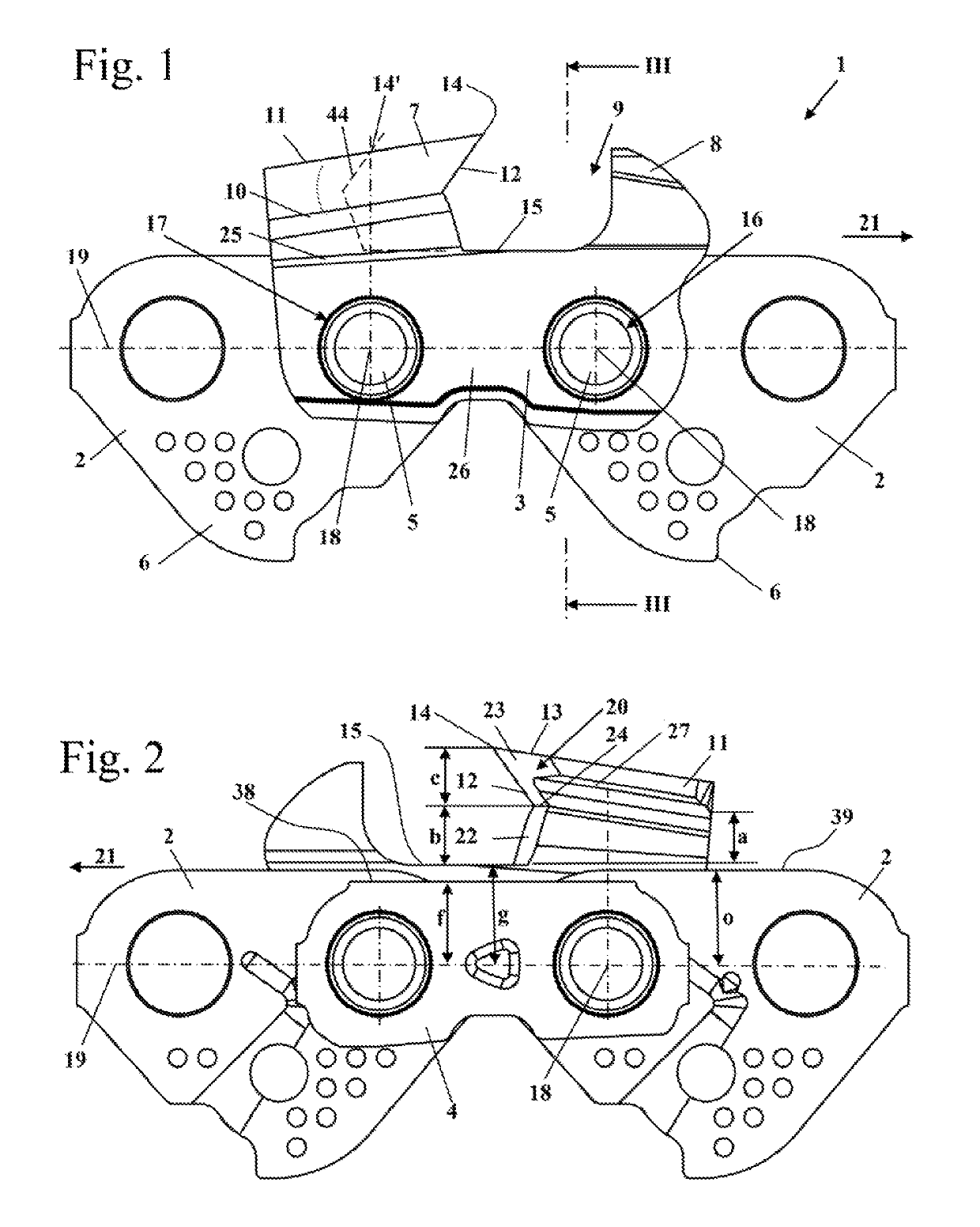
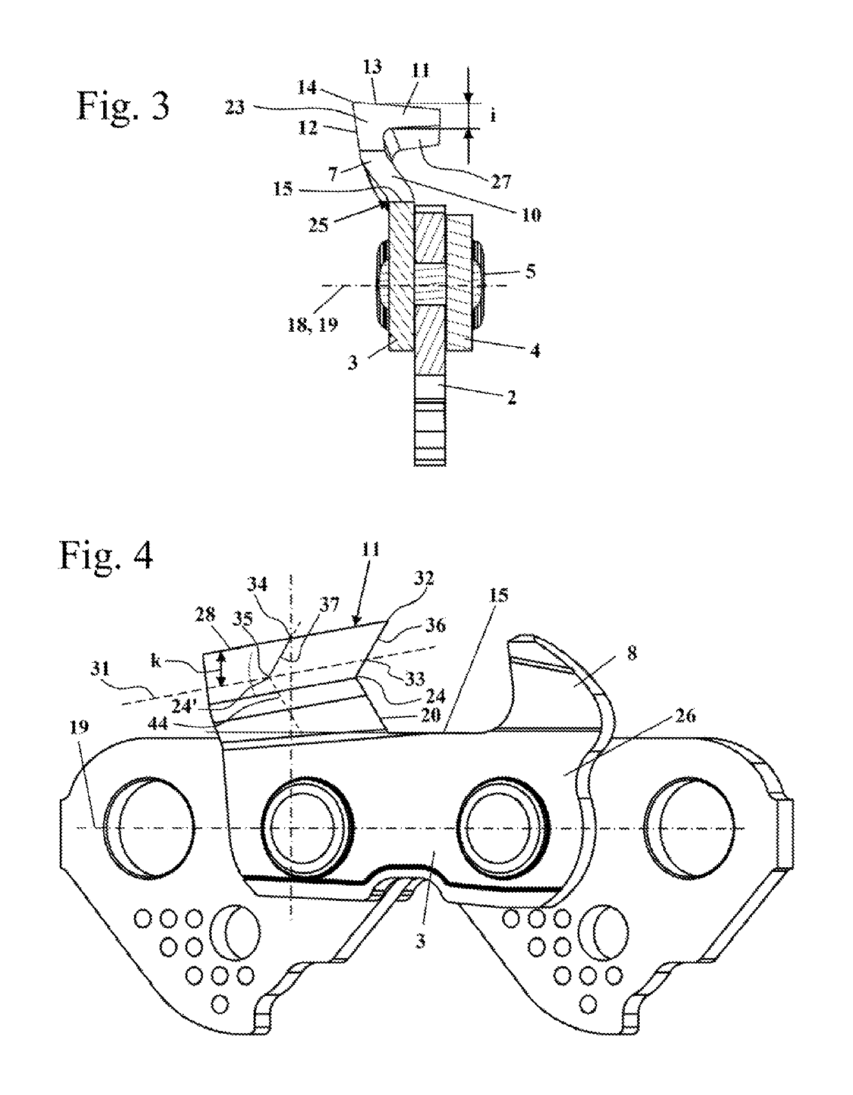
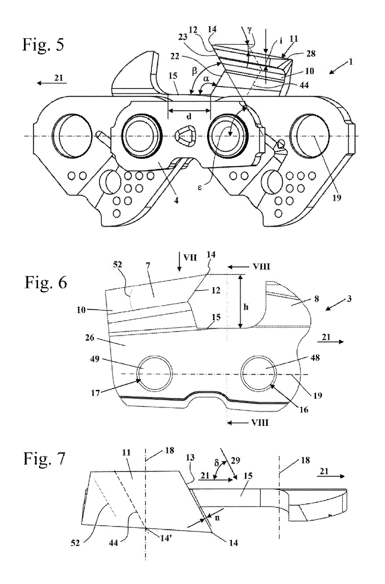
[0013]In a preferred realization, the sharpened cutting surface has a first cutting surface section and a second cutting surface section which extends at an angle to the first cutting surface section. The sharpened cutting surface is the surface of the cutting member which is filed during resharpening. The first cutting surface section and the second cutting surface section are planar surfaces in a preferred manner. The second cutting surface section is realized at least in part on the roof section. The first cutting surface section and the second cutting surface section adjoin one another at a cutting surface edge. The cutting surface edge is arranged such that the distance between the cutting surface edge and the plane of the contact surface is no more than 0.2 mm greater than the smallest distance, measured perpendicularly to the plane of the contact surface, between the underside of the roof section and the plane of the contact surface. The distance, measured perpendicularly to the contact surface, is measured, in this case, respectively to the plane of the contact surface, that is, to the extension of the contact surface. In a particularly preferred configuration, the distance between the cutting surface edge and the plane of the contact surface is smaller than the smallest distance between the underside of the roof section and the plane of the contact surface or equal to the smallest distance between the underside of the roof section and the plane of the contact surface. As a result, the cutting tooth is able to be re-sharpened close to the end, located at the rear in the running direction, of the cutting tooth without the cutting surface edge creeping into the roof section during resharpening.
[0018]A depth delimiter is advantageously arranged before the cutting tooth. A cutout is advantageously formed between the cutting tooth and the depth delimiter, the cutout being delimited at least in part in the direction of the bearing point plane by the contact surface. In a preferred configuration, the cutout is delimited fully in the direction of the bearing point plane by the contact surface such that the entire bottom of the cutout is formed by the contact surface. As a result, a very long contact surface and as a result secure guiding of a file during resharpening can be achieved in a simple manner. However, it can also be provided that the contact surface takes up only the region of the bottom of the cutout arranged directly before the cutting surface.
[0020]It is advantageously provided for a file for filing a cutting tooth of a saw chain that the file has an unhewn guide surface in cross section and at least one file surface which adjoins the guide surface in the circumferential direction. The file is able to be placed on the contact surface with the rough guide surface. The file surface, which adjoins the guide surface, is advantageously provided to abut against the cutting surface and to machine the cutting surface. As a result of the file surface directly adjoining the unhewn guide surface, and the guide surface itself being unhewn, it is possible to achieve in a simple manner that the contact surface is lengthened during resharpening and its alignment in this case is maintained. As a result, simple and precise resharpening can be made possible even for an inexperienced user. The width of the file, measured parallel to the guide surface, is enlarged advantageously in at least one region of the cross section of the file as the distance from the guide surface increases. As a result, an undercut can be produced in a simple manner on the cutting surface without the region of the connection between the cutting tooth and the basic body of the cutting member being unduly weakened. In a preferred manner, the distance between the file surface and a center plane of the file, which includes the longitudinal center axis of the file and extends perpendicularly to the guide surface, is increased in a first region of the file as the distance from the guide surface increases. It is advantageously provided in a second region of the file, the distance of which from the guide surface is greater than the distance of the first region from the guide surface, that the distance between the file surface and the center plane of the file is reduced as the distance from the guide surface increases. As a result, an undercut is generated on the cutting surface by the first region and the second region of the file.
[0022]It is provided in particular for a cutting member which has two cutting surfaces which are aligned at an angle to one another and in a preferred manner extend in each case in a flat manner, that the file has a second file surface which adjoins the first file surface in the circumferential direction, the guide surface enclosing with the first file surface a first angle which is more than 90°, and the guide surface enclosing with the second file surface a second angle which is less than 90°. As a result, a comparatively wide connection between the cutting tooth and the basic body of the cutting member and at the same time an advantageous cutting angle can be achieved. In an advantageous manner, the first file surface forms the first region of the file and the second file surface forms the second region of the file.
[0024]In an advantageous manner, the first file surface and the second file surface have the same edge dimension, measured in the circumferential direction. In a preferred configuration, the file has two unhewn guide surfaces which are located opposite one another, two first file surfaces which are located opposite one another and two second file surfaces which are located opposite one another. As a result, the file is able to be utilized for resharpening in at least two orientations. In a particularly preferred configuration, the file has a hexagonal cross section. The width of the guide surface is advantageously at least 3 mm. As a result, the file is guided well by the guide surface.


