File for filing the cutting tooth of a saw chain

a technology for filing and cutting teeth, which is applied in the direction of filing/rasping equipment, metal-working equipment, sawing tools dressing arrangements, etc., can solve the problems of easy loss of cutting teeth in the region of connection to the basic body of the cutting member, clear change of cutting angle, etc., and achieves the effect of convenient holding on to the fil

Active Publication Date: 2021-05-18
ANDREAS STIHL AG & CO KG
View PDF65 Cites 0 Cited by
  • Summary
  • Abstract
  • Description
  • Claims
  • Application Information

AI Technical Summary

Benefits of technology

[0005]It is an object of the invention is to provide a file for filing the cutting tooth of a saw chain which allows simple resharpening.
[0007]It is provided for a file for filing a cutting tooth of a saw chain that the file has in cross section an unhewn guide surface and at least one file surface which adjoins the guide surface in the circumferential direction. The file is able to be placed on the support surface with the unhewn guide surface. The file surface, which adjoins the guide surface, can advantageously be provided to abut against the cutting surface and to machine the cutting surface. As a result of the file surface directly adjoining the unhewn guide surface, and the guide surface itself being unhewn, it is possible to achieve in a simple manner that the support surface is lengthened during resharpening and its alignment in this case is maintained. As a result, simple and precise resharpening can be made possible even for an inexperienced user. The width of the file, measured parallel to the guide surface, is enlarged advantageously in at least one region of the cross section of the file as the distance from the guide surface increases. As a result, an undercut can be produced in a simple manner on the cutting surface without the region of the connection between the cutting tooth and the basic body of the cutting member being unduly weakened. In a preferred manner, the distance between the file surface and a center plane of the file, which includes the longitudinal center axis of the file and extends perpendicularly to the guide surface, is increased in a first region of the file as the distance from the guide surface increases. It is advantageously provided in a second region of the file, the distance of which from the guide surface is greater than the distance of the first region from the guide surface, that the distance between the file surface and the center plane of the file is reduced as the distance from the guide surface increases. As a result, an undercut is generated on the cutting surface by the first region and the second region of the file.
[0008]It is provided in particular for a cutting member which has two cutting surfaces which are aligned at an angle to one another and in a preferred manner extend in each case in a flat manner, that the file has a second file surface which adjoins the first file surface in the circumferential direction, the guide surface enclosing with the first file surface a first angle which is more than 90°, and the guide surface enclosing with the second file surface a second angle which is less than 90°. As a result, a comparatively wide connection between the cutting tooth and the basic body of the cutting member and at the same time an advantageous cutting angle can be achieved. In an advantageous manner, the first file surface forms the first region of the file and the second file surface forms the second region of the file.
[0010]In an advantageous manner, the first file surface and the second file surface have the same edge dimension, measured in the circumferential direction. In a preferred configuration, the file has two unhewn guide surfaces which are located opposite one another, two first file surfaces which are located opposite one another and two second file surfaces which are located opposite one another. As a result, the file is able to be utilized for resharpening in at least two orientations. In a particularly preferred configuration, the file has a hexagonal cross section. The width of the guide surface is advantageously at least 3 mm. As a result, the file is guided well by the guide surface.
[0023]In an alternative configuration, it is advantageously provided that the file has, in the second longitudinal section, at least one, in particular two surfaces that are inclined with respect to the longitudinal direction. Accordingly, the file is formed in a chamfered manner at the surfaces that are inclined with respect to the longitudinal direction. Particularly preferably, two surfaces that are inclined with respect to the longitudinal direction converge at an edge. The edge preferably forms the free end of the file. Alternatively or additionally, provision can be made for the file to have a longitudinal slot in the second longitudinal section. Advantageously, the longitudinal slot is arranged parallel or perpendicularly to at least one guide surface. The longitudinal slot provides visual feedback about the position of the at least one guide surface. At the same time, the longitudinal slot makes it easier to hold on to the file, since grip is increased by the longitudinal slot.

Problems solved by technology

At the same time, the operator must ensure when filing that he does not guide the file too far in the direction of the bearing position plane as this can result in weakening the cutting tooth in the region of the connection to the basic body of the cutting member.
This is difficult in particular for inexperienced operators.
Even small errors in the positioning of the round file give rise to a clear change in the cutting angle.

Method used


Image

  • File for filing the cutting tooth of a saw chain
  • File for filing the cutting tooth of a saw chain
  • File for filing the cutting tooth of a saw chain

Examples


Embodiment Construction

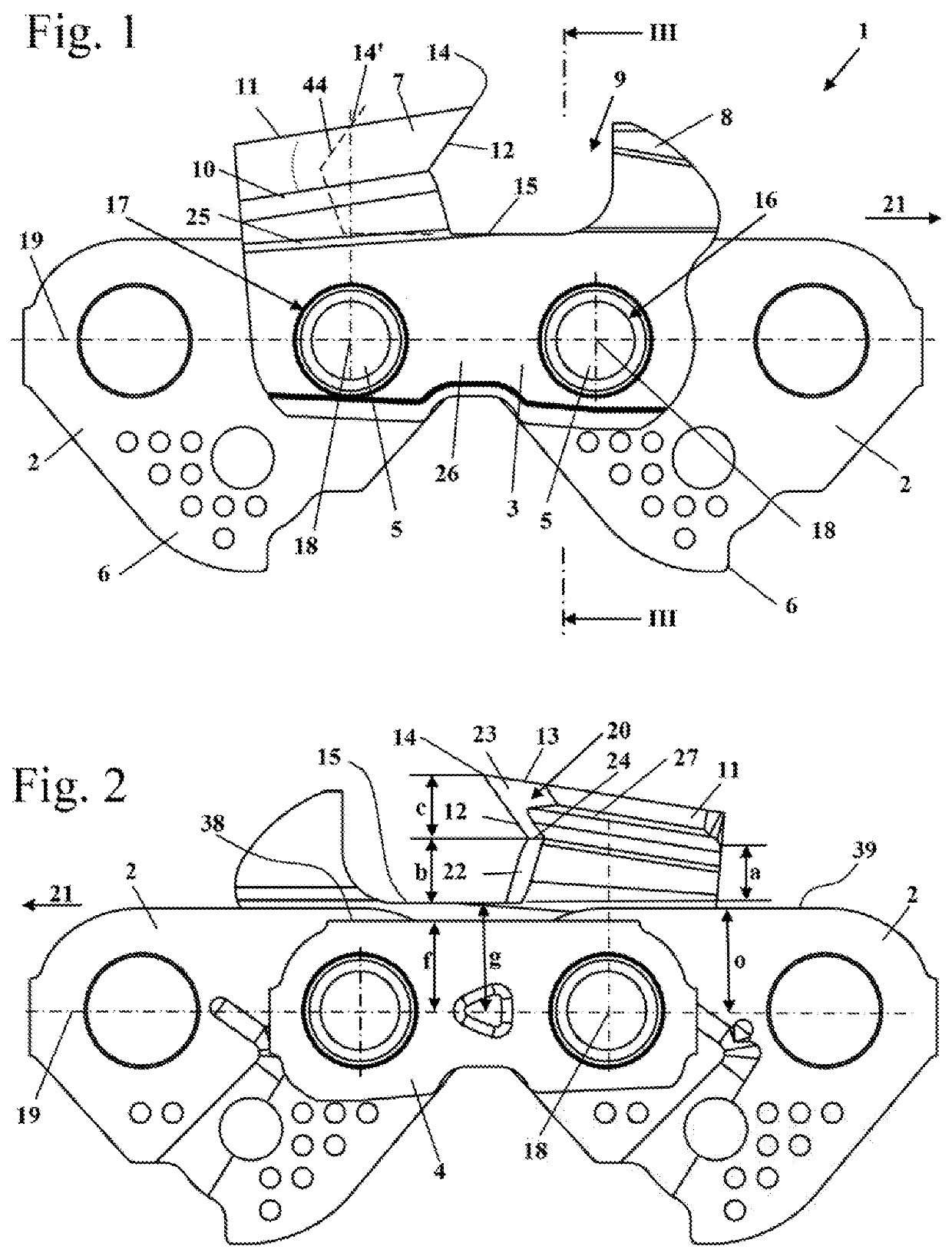
[0051]FIG. 1 shows a side view of a section of a saw chain 1. The saw chain 1 has drive links 2 and cutting members 3 which are connected together in an articulated manner via connecting pins 5. The saw chain 1 is provided as a tool for a power saw in which the saw chain 1 is to be arranged circulating around a guide rail. In this case, drive bases 6 of the drive links 2 project into a guide groove of the guide rail and are driven by a drive pinion of the power saw. The saw chain 1, in this case, is moved in a running direction 21 circulating around the guide rail. The connecting pins 5 are arranged at bearing points of the cutting member 3. A front bearing point 16, which is arranged at the front in the running direction 21, and a rear bearing point 17, which is located at the rear in the running direction 21, are provided. The bearing points 16 and 17 each have longitudinal center axes 18 which form the pivot axes of the members of the saw chain 1. The longitudinal center axes 18 ...


PUM


Abstract

The disclosure relates to a file for filing a saw tooth of a saw chain. The file includes a file body defining a circumferential direction and a circumference. The file body, in a cross section, has an unhewn guide surface and a file surface adjoining the unhewn guide surface in the circumferential direction. The unhewn guide surface extends over at least ⅙ of the circumference in the cross section.

Description

CROSS REFERENCE TO RELATED APPLICATIONS[0001]This application is a continuation-in-part application of patent application Ser. No. 15 / 959,103, filed Apr. 20, 2018, which, in turn, claims priority of European patent application no. 17 400 020.8, filed Apr. 20, 2017, the entire contents of both applications are incorporated herein by reference.FIELD OF THE INVENTION[0002]The invention relates to a file for filing the cutting tooth of a saw chain.BACKGROUND OF THE INVENTION[0003]CA 2,054,617 A1 discloses a cutting member of a saw chain which is to be re-sharpened using a grinding wheel. During resharpening there is a planar surface on a cutout between depth limiter and cutting tooth. The cutting surface formed on the cutting tooth has a cutting surface edge which in the resharpening state shown is arranged directly on the underside of the roof section of the cutting member. If the cutting tooth is re-sharpened further and at the same time the grinding wheel is moved parallel to the bea...

Claims


Application Information

Patent Timeline
Patent Type & Authority Patents(United States)
IPC IPC(8): B23D63/16
CPCB23D63/162B23D71/04
Inventor LUX, THOMASHOLLMEIER, FRIEDRICHMAIER, GEORGSTAPEL, BERTILGRAMS, TOBIASALTHOFF, NORBERT
Owner ANDREAS STIHL AG & CO KG
Why Eureka
Try Eureka