Ultrasonic robotic tool actuation

a robotic tool and ultrasonic technology, applied in the field of ultrasonic robotic tool actuation, can solve the problem of longitudinal translation of the yok

Active Publication Date: 2019-11-12
CILAG GMBH INT
View PDF18 Cites 426 Cited by
  • Summary
  • Abstract
  • Description
  • Claims
  • Application Information

AI Technical Summary

Benefits of technology

[0009]Surgical methods are also provided, and in one embodiment the method includes actuating a motor on a driver tool of a surgical robot to cause the motor to apply a force to an actuator on a surgical tool. Movement of the actuator can cause a yoke disposed within a housing of the surgical tool to translate linearly about a shaft assembly extending through the housing. Translation of the yoke can cause a clamp arm on an end effector of the surgical tool to move from an open position to a closed position to thereby engage tissue between the clamp arm and a blade.

Problems solved by technology

Rotation of the first actuator can cause a lead screw disposed within the housing to rotate, and rotation of the lead screw can cause longitudinal translation of the yoke.

Method used


Image

  • Ultrasonic robotic tool actuation
  • Ultrasonic robotic tool actuation
  • Ultrasonic robotic tool actuation

Examples


Embodiment Construction

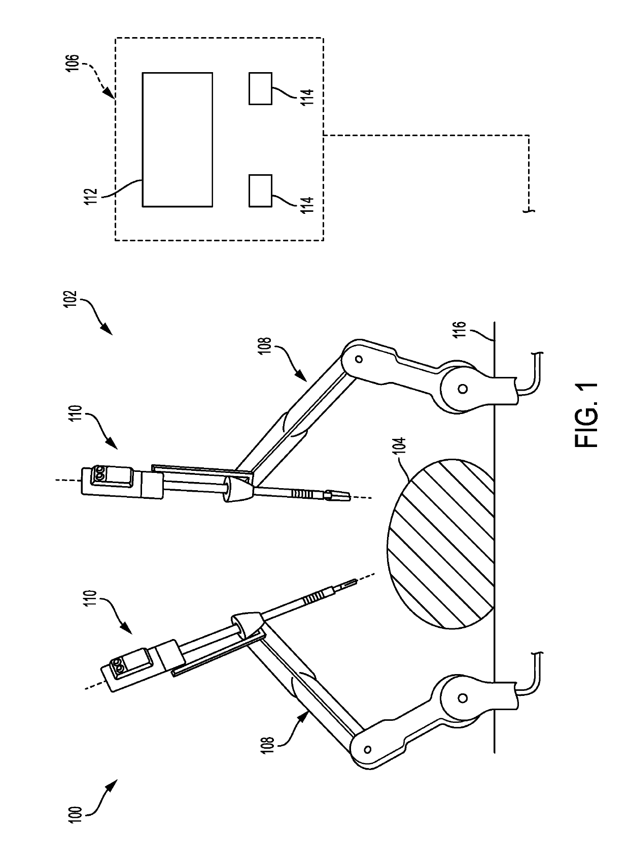
[0027]Certain exemplary embodiments will now be described to provide an overall understanding of the principles of the structure, function, manufacture, and use of the devices and methods disclosed herein. One or more examples of these embodiments are illustrated in the accompanying drawings. Those skilled in the art will understand that the devices and methods specifically described herein and illustrated in the accompanying drawings are non-limiting exemplary embodiments and that the scope of the present invention is defined solely by the claims. The features illustrated or described in connection with one exemplary embodiment may be combined with the features of other embodiments. Such modifications and variations are intended to be included within the scope of the present invention.

[0028]Further, in the present disclosure, like-named components of the embodiments generally have similar features, and thus within a particular embodiment each feature of each like-named component is...


PUM


Abstract

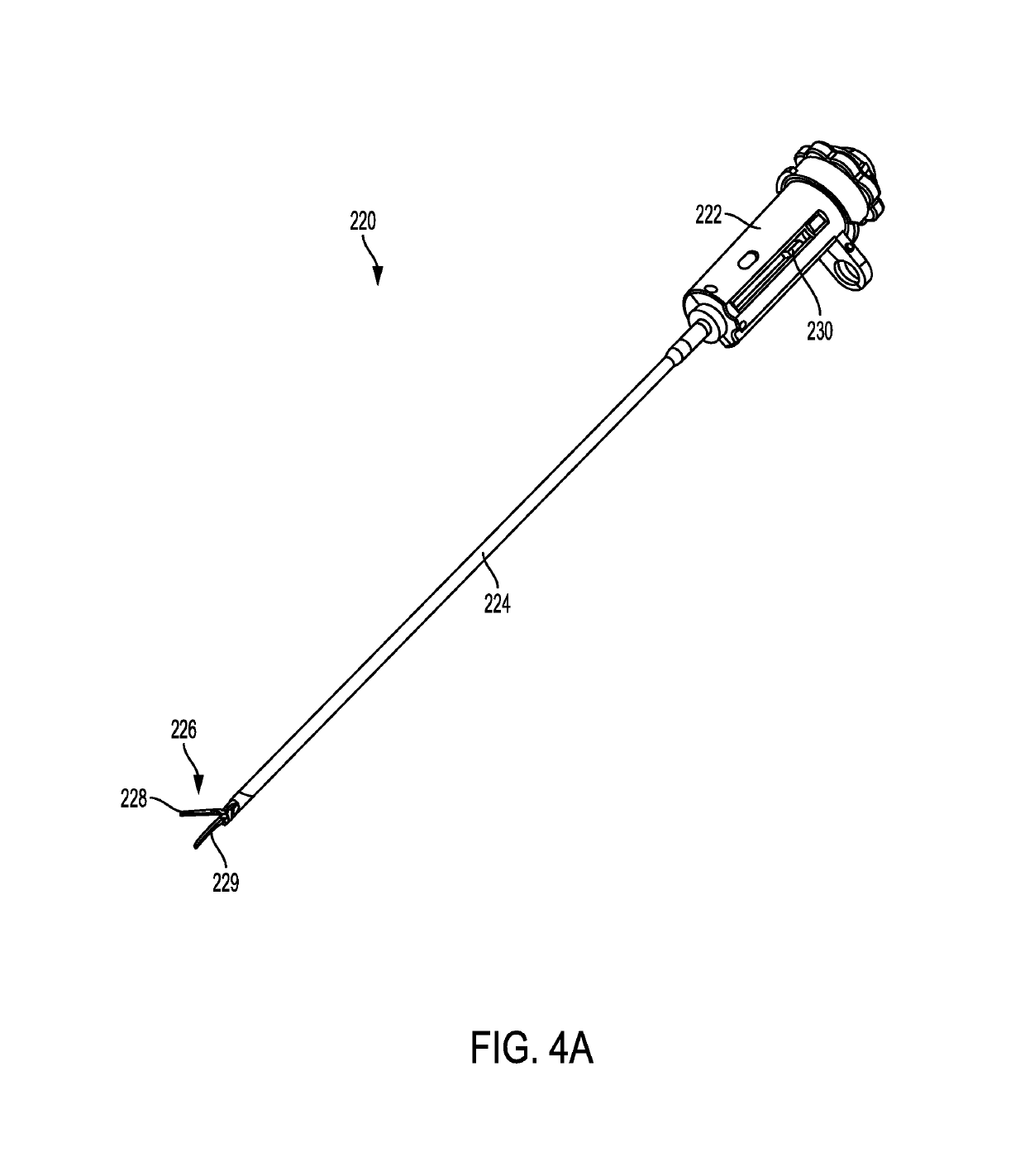
Described herein include various embodiments of a tool assembly for performing endoscopic surgery that can be used manually and / or with a robotic surgical system. The tool assembly can include a shaft assembly that extends from a housing of the tool assembly. A distal end of the shaft can include an end effector that includes a clamp arm pivotally coupled to a blade for cutting and / or sealing tissue. Pivoting of the clamp arm between the open and closed configurations can be caused by movement of a yoke that is slidably disposed within the housing of the tool assembly. For example, the yoke can be caused to move by one or more outputs (e.g., a manual output, a rotary output, and / or a linear mechanical output). Furthermore, some tool assembly embodiments can include a biasing system that biases the yoke such that the clamp arm is in the open configuration. In some embodiments, the tool assembly can be configured for tissue spread dissection using the clamp arm and blade.

Description

FIELD OF THE INVENTION[0001]The present disclosure relates generally to methods, systems, and devices for controlling the pivoting of a clamp arm of an end effector of a surgical tool.BACKGROUND OF THE INVENTION[0002]Minimally invasive surgical (MIS) instruments are often preferred over traditional open surgical devices due to the reduced post-operative recovery time and minimal scarring. Laparoscopic surgery is one type of MIS procedure in which one or more small incisions are formed in the abdomen and a trocar is inserted through the incision to form a pathway that provides access to the abdominal cavity. The trocar is used to introduce various instruments and tools into the abdominal cavity, as well as to provide insufflation to elevate the abdominal wall above the organs. The instruments and tools can be used to engage and / or treat tissue in a number of ways to achieve a diagnostic or therapeutic effect. Endoscopic surgery is another type of MIS procedure in which elongate flexi...

Claims


Application Information

Patent Timeline
Patent Type & Authority Patents(United States)
IPC IPC(8): A61B34/35A61N7/02A61B17/32A61B34/30A61B18/00A61B17/00A61B17/29A61B34/00
CPCA61B17/320092A61N7/02A61B34/30A61B34/35A61B34/70A61B2017/0046A61B2018/0063A61B2017/320095A61B2017/2912A61B2034/305A61B2017/00402A61B2017/00477A61B2018/00601A61B2017/320094A61B18/04A61B2018/00607
Inventor KIRK, JEFFERYFELDER, KEVIN D.
Owner CILAG GMBH INT
Why Eureka
Try Eureka