
Tripod universal joint fairway heat treatment device and heat treatment method
a technology of heat treatment device and universal joint, which is applied in the field of heat treatment, can solve the problems of excessive clearance between the polished bearing ring and the section b working area, the deformation phenomenon of the inability to install the three bearing rings, etc., and achieves the effect of improving the quality of the quenching surface, reducing the risk of damage, and improving the qualified rate of products and safety performan
- Summary
- Abstract
- Description
- Claims
- Application Information
AI Technical Summary
Benefits of technology
Problems solved by technology
Method used
Image

Examples
embodiment i
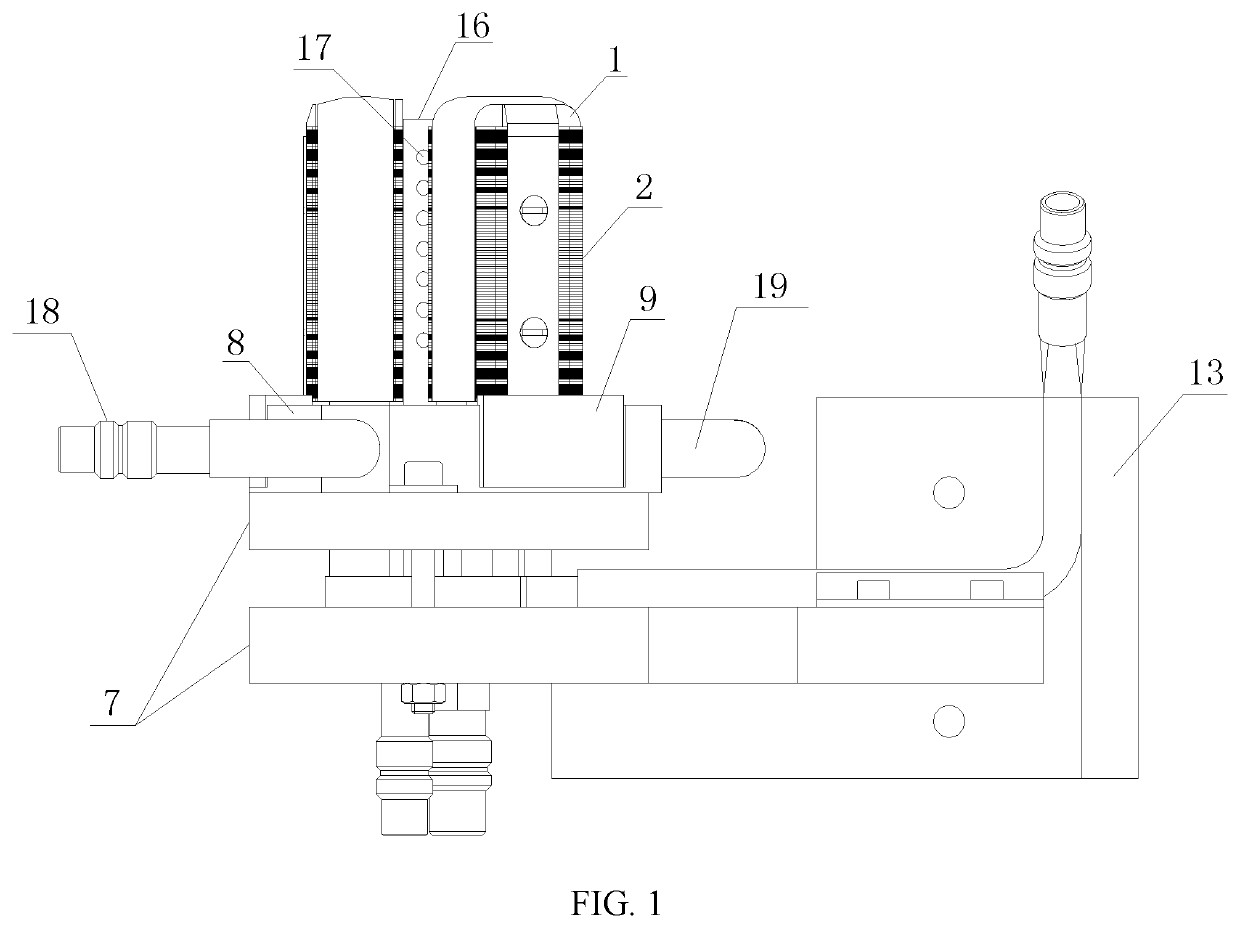
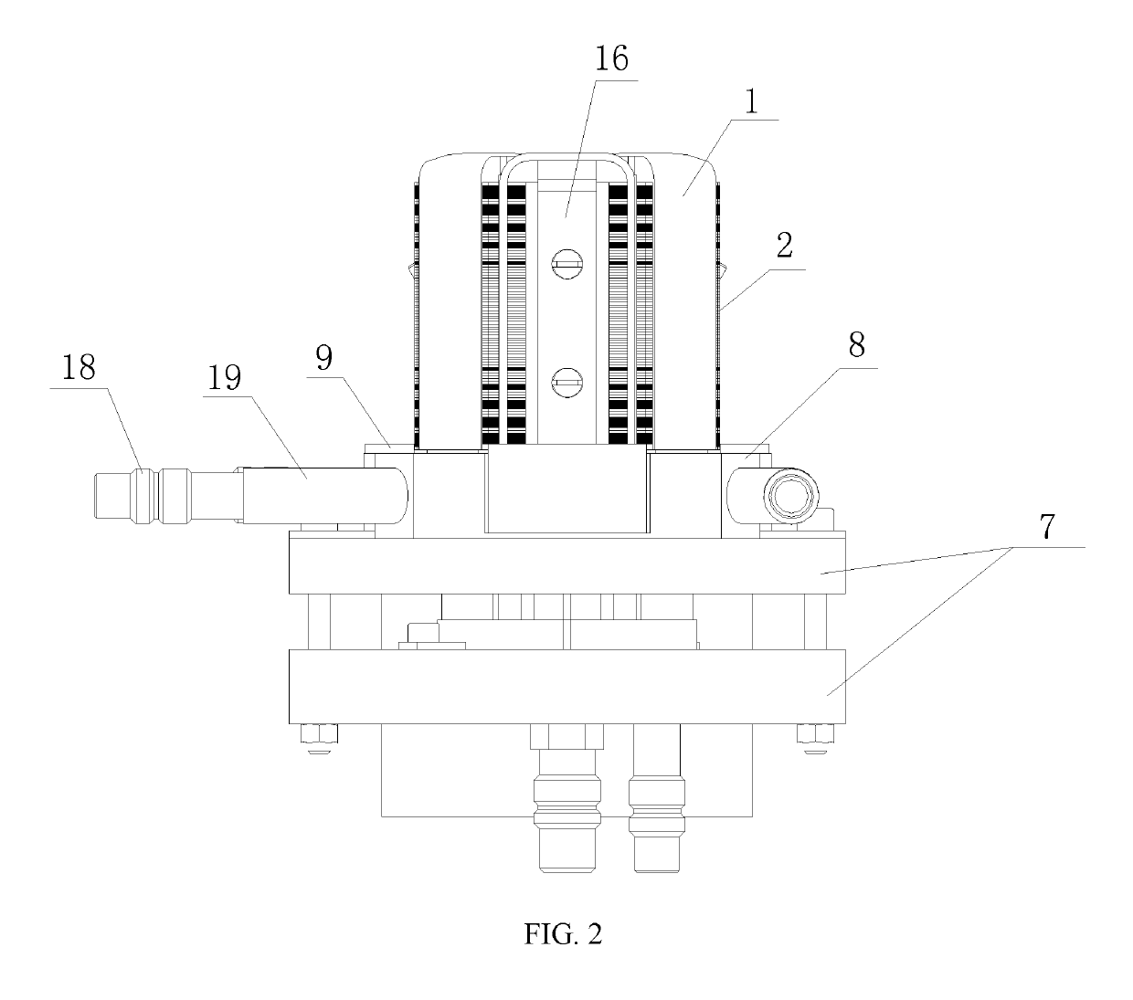
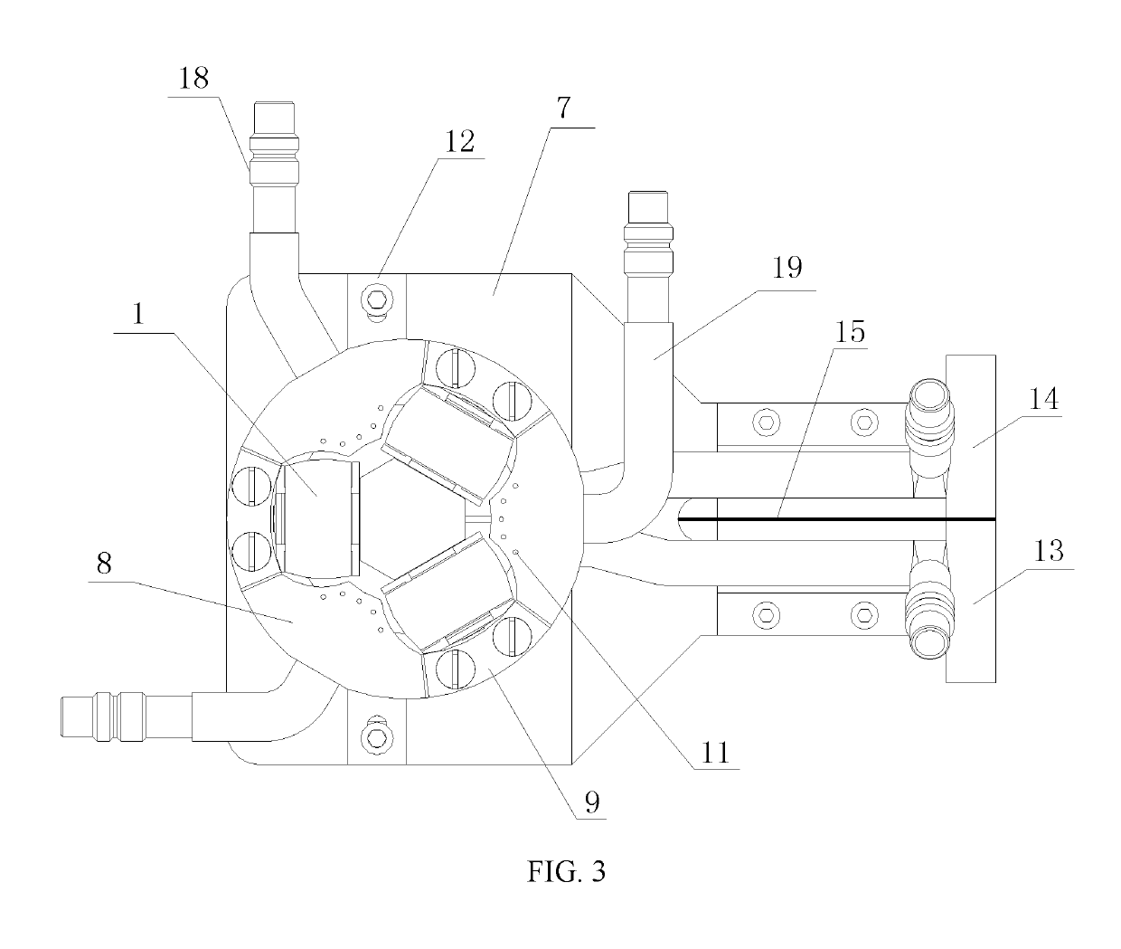
[0059]A tripod universal joint fairway heat treatment device in the present invention is further described below in combination with drawings. As shown in FIG. 1, FIG. 2, FIG. 3, FIG. 4, FIG. 5 and FIG. 6, the tripod universal joint fairway heat treatment device includes a fixing plate 7, effective coils 1, a magnetizer 2, opening positioning water spraying rings 8, a positive busbar 13 and a negative busbar 14.
[0060]As shown in FIG. 4, FIG. 7 and FIG. 8, the magnetizer 2 and magnetic conductive insulation sheets 6 are arranged on the effective coils 1; three effective coils 1 are arranged; an included angle between every two adjacent effective coils 1 is 120 degrees; a rubber stick 16 is also arranged on the fixing plate 7; the three effective coils 1 are encircled to form a containing cavity for receiving the rubber stick 16; the rubber stick 16 is of a hollow structure; a water outlet 17 is formed in the rubber stick 16; and a shape of the effective coils 1 is a U shape with a do...
embodiment ii
[0093]Differences of the present embodiment from embodiment I are as follows: a stainless steel positioning block 9 is arranged on the opening positioning water spraying ring 8; an upper surface of the stainless steel positioning block 9 protrudes out of an upper surface of the opening positioning water spraying ring 8; a mounting groove 10 for receiving the stainless steel positioning block 9 is formed on the opening positioning water spraying ring 8; and the stainless steel positioning block 9 is fixed in the mounting groove 10 through screws.
[0094]Totally three stainless steel supporting blocks are uniformly distributed on the opening positioning water spraying ring 8. Through the arrangement of the stainless steel supporting blocks, a phenomenon that the effective coils 1 are exposed and directly contacted with the inner cavity of the workpiece to generate ignition because metals on the surface of the opening positioning water spraying ring 8 are excessively worn and an upper ed...
PUM
| Property | Measurement | Unit |
|---|---|---|
| thickness | aaaaa | aaaaa |
| included angle | aaaaa | aaaaa |
| included angle | aaaaa | aaaaa |
Abstract
Description
Claims
Application Information