Tripod universal joint fairway heat treatment device and heat treatment method

a technology of heat treatment device and universal joint, which is applied in the field of heat treatment, can solve the problems of excessive clearance between the polished bearing ring and the section b working area, the deformation phenomenon of the inability to install the three bearing rings, etc., and achieves the effect of improving the quality of the quenching surface, reducing the risk of damage, and improving the qualified rate of products and safety performan

Active Publication Date: 2018-04-26
ZHEJIANG ODM TRANSMISSION TECH
View PDF3 Cites 1 Cited by
  • Summary
  • Abstract
  • Description
  • Claims
  • Application Information

AI Technical Summary

Benefits of technology

[0014]Magnetic field intensity in the two-end induction areas is weakened by the magnetic conductive insulation sheets, so that magnetic lines of force in the two-end induction areas are sparse. In an actual using process, because magnetic fields at the opening and the bottom of the fairway are weakened, the deformation after quenching is correspondingly weakened, thereby achieving effects of increasing the deformation in the middle of the fairway and decreasing the deformation at the two ends.
[0028]Compared with the prior art, the tripod universal joint fairway heat treatment method provided by the present invention has the following advantages that deformation of each part of the fairway can be effectively controlled when the tripod universal joint fairway is subjected to heat treatment, so that quenching quality of the fairway is greatly improved, and the tripod universal joint is convenient to be assembled during subsequent assembly.

Problems solved by technology

However, an intermediate frequency quenching principle determines that a material after heat treatment may cause a deformation phenomenon.
A problem brought by deformation of the inner cavity is that the three bearing rings cannot be installed into the chutes according to set sizes, so an outer diameter of each bearing ring needs to be polished to be small enough to pass through the section a area of the opening before the bearing ring is assembled.
However, a problem brought by this manner is that an assembling clearance between the polished bearing ring and the section b working area is too large and exceeds a reasonable range.
In a loading travel process, abnormal sound and vibration during transmission are caused due to too large clearances between the bearing rings and the chutes of the universal joint, and even premature failure of the universal joint may be caused after a long time.
After used for a long time, the opening positioning device is easily rubbed by the opening of the tripod universal joint and worn, and overall positioning accuracy of the tripod universal joint is reduced, so the bottom of the tripod universal joint fairway is contacted with inductor accessories and worn, causing that the tripod universal joint is directly contacted with an effective coil to generate ignition and a copper tube of the effective coil is broken, thereby shortening service life of the quenching inductor.

Method used


Image

  • Tripod universal joint fairway heat treatment device and heat treatment method
  • Tripod universal joint fairway heat treatment device and heat treatment method
  • Tripod universal joint fairway heat treatment device and heat treatment method

Examples


embodiment i

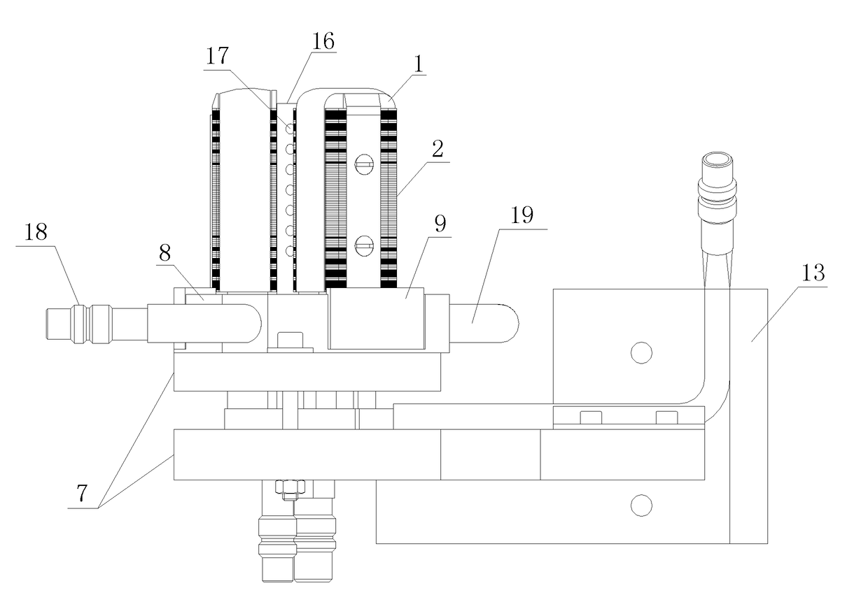
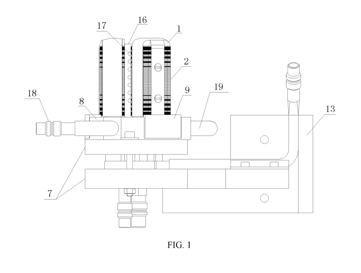
[0059]A tripod universal joint fairway heat treatment device in the present invention is further described below in combination with drawings. As shown in FIG. 1, FIG. 2, FIG. 3, FIG. 4, FIG. 5 and FIG. 6, the tripod universal joint fairway heat treatment device includes a fixing plate 7, effective coils 1, a magnetizer 2, opening positioning water spraying rings 8, a positive busbar 13 and a negative busbar 14.

[0060]As shown in FIG. 4, FIG. 7 and FIG. 8, the magnetizer 2 and magnetic conductive insulation sheets 6 are arranged on the effective coils 1; three effective coils 1 are arranged; an included angle between every two adjacent effective coils 1 is 120 degrees; a rubber stick 16 is also arranged on the fixing plate 7; the three effective coils 1 are encircled to form a containing cavity for receiving the rubber stick 16; the rubber stick 16 is of a hollow structure; a water outlet 17 is formed in the rubber stick 16; and a shape of the effective coils 1 is a U shape with a do...

embodiment ii

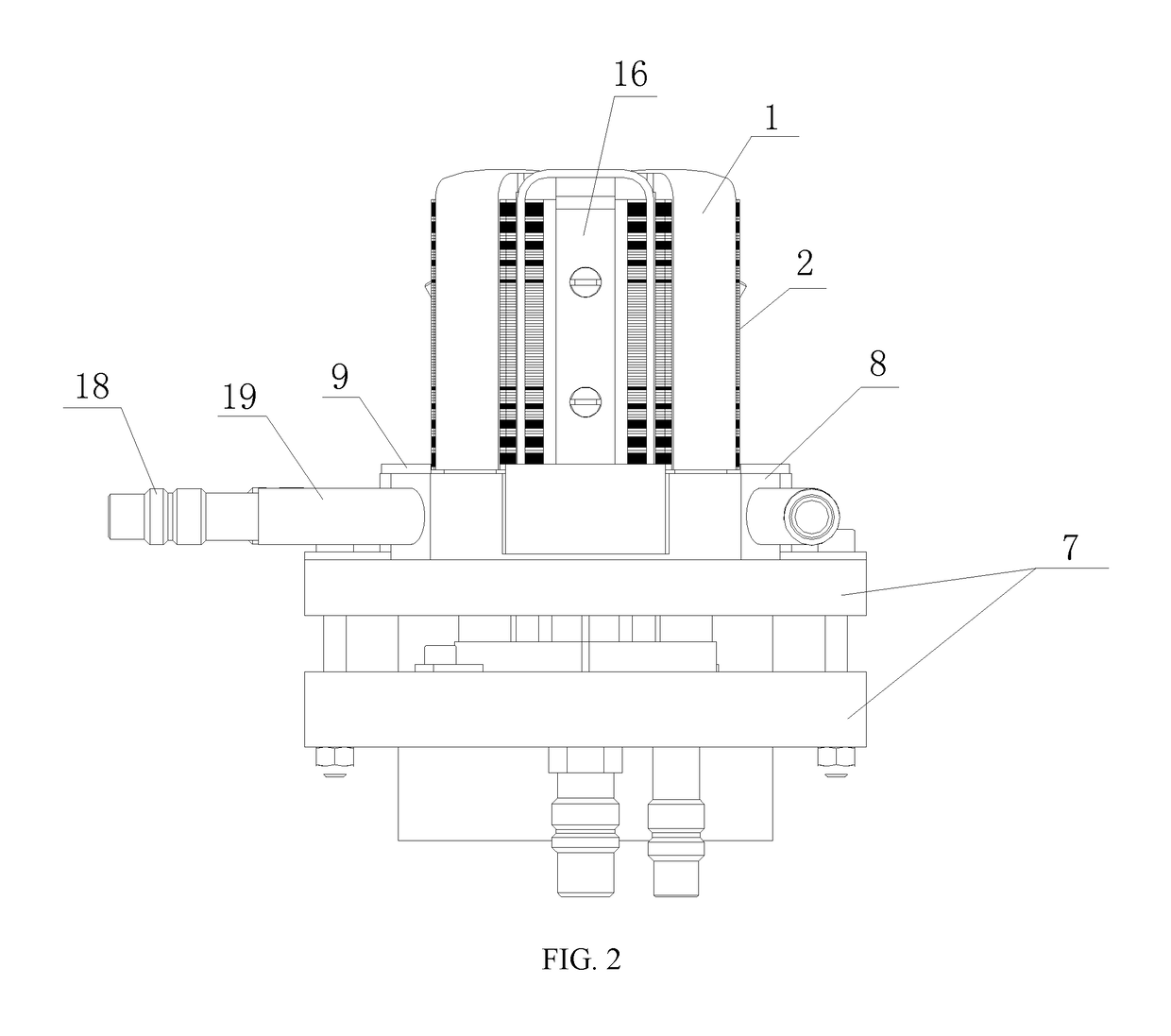
[0093]Differences of the present embodiment from embodiment I are as follows: a stainless steel positioning block 9 is arranged on the opening positioning water spraying ring 8; an upper surface of the stainless steel positioning block 9 protrudes out of an upper surface of the opening positioning water spraying ring 8; a mounting groove 10 for receiving the stainless steel positioning block 9 is formed on the opening positioning water spraying ring 8; and the stainless steel positioning block 9 is fixed in the mounting groove 10 through screws.

[0094]Totally three stainless steel supporting blocks are uniformly distributed on the opening positioning water spraying ring 8. Through the arrangement of the stainless steel supporting blocks, a phenomenon that the effective coils 1 are exposed and directly contacted with the inner cavity of the workpiece to generate ignition because metals on the surface of the opening positioning water spraying ring 8 are excessively worn and an upper ed...


PUM

PropertyMeasurementUnit
thicknessaaaaaaaaaa
included angleaaaaaaaaaa

Abstract

The present disclosure discloses a tripod universal joint fairway heat treatment device. A magnetizer includes a middle induction area and two-end induction areas, wherein the middle induction area includes magnetic conductive sheets stacked together; and the two-end induction areas include magnetic conductive sheets and magnetic conductive insulation sheets crosswise stacked together. Controllable deformation of an inner cavity fairway of a tripod universal joint during intermediate frequency quenching is realized by changing an arrangement form of the magnetic conductive sheets in the magnetizer, thereby avoiding a condition that three pivot shafts and bearing rings cannot be installed due to excessive deformation at a fairway opening after quenching, and greatly improving a qualified rate of products and safety performance of the products during use.

Description

TECHNICAL FIELD[0001]The present invention relates to the field of heat treatment, and more specifically, to a tripod universal joint fairway heat treatment device and a heat treatment method.BACKGROUND OF THE INVENTION[0002]A constant velocity universal joint for automobiles, as an important member for connecting and transmitting a driving shaft between an output shaft of a gearbox and a wheel hub, can be classified into a fixed constant velocity universal joint and a telescopic sliding constant velocity universal joint according to operating properties of the universal joint. A tripod universal joint is one of the most common forms in the telescopic sliding constant velocity universal joint.[0003]The tripod universal joint is composed of a three-column groove shell, a retainer ring, bearing rings, roller pins and a tripod. A main function of the tripod universal joint is to connect two shafts between which an included angle is formed or of which mutual positions are changed, so th...

Claims


Application Information

Patent Timeline
Patent Type & Authority Applications(United States)
IPC IPC(8): C21D9/00C21D1/42C21D1/667
CPCC21D9/0068C21D1/42C21D1/667Y02P10/25
Inventor WANG, LIJUNWANG, WEIKAIFAN, YOUSHENGLU, LEIMA, BAIBINZENG, LINGYI
Owner ZHEJIANG ODM TRANSMISSION TECH
Why Eureka
Try Eureka