Pneumatic radial tire

a radial tire and pneumatic technology, applied in the direction of pneumatic tyre reinforcements, off-road vehicle tyres, vehicle components, etc., can solve the problems of reducing the hoop effect, limiting the wrapping property of the tread surface, and the tire cannot develop sufficient driving for

Active Publication Date: 2013-06-06
TOYO TIRE & RUBBER CO LTD
View PDF4 Cites 49 Cited by
  • Summary
  • Abstract
  • Description
  • Claims
  • Application Information

AI Technical Summary

Benefits of technology

[0024]In detail, by the fact that the steel belt layer reinforcing the tread part includes three or less layers, rigidity of the tread surface is decreased, thereby deformation of the block can be made easy. Furthermore, by the fact that the first block and the second block are provided in a grounding edge region of the tread, by making the grounding edge in a concavo-convex shape in a tire circumferential direction, concentrated load is liable to be acted to the second block extending to the outside in the tire width direction. As a result, the second block is liable to be sunk toward an inner side in the tire radial direction. By the fact that the annular region in which plural projections are provided side by side in a circumferential direction and the outer thin wall part and the inner thin wall part, extending along the inner circumferential edge and the outer circumferential edge are appropriately arranged on the side wall part as described above, when external force is acted from a road surface under low inner pressure conditions, the outer thin wall part and the inner thin wall part become joints of deformation, and road surface follow-up performance is improved. That is, by the deformation of the second block by the concentrated load, the outer thin wall part compresses or buckling-deforms, and the inner thin wall part stretches or expansion-deforms. Therefore, deformation force of the second block can be parried to the inner side in the tire radial direction, and depression deformation of the second block can become easy. As a result, deformation of the block on the tread surface can be increased under low inner pressure conditions, thereby improving road surface follow-up performance on uneven road surface such as rocky area, and running performance can be enhanced.

Problems solved by technology

Thus, in the case of running the rocky area with a tire having low inner pressure, particularly in the case of running through rocky mountain composed of piled large rocks having a diameter of 1 meter or more, the tire cannot develop sufficient driving force under grounding conditions that blocks on a tread surface contact the surface of rocks in a form of line contact or point contact.
Therefore, for example, in the case of grounding acute-angled rocks, there is a limit to increase wrapping property by the blocks on the tread surface.
It is considered to weaken the hoop effect by reducing the number of lamination of steel belt layers or decreasing a diameter of a steel cord in a belt layer.
However, where the hoop effect is weakened, running performance on ordinary paved road and non-paved road, and load resistance are reduced.
Thus, there is a limit to weaken the hoop effect.
For this reason, wrapping property on the tread surface tends to be deteriorated.
However, this document discloses that the projection in a circumferential direction and the projections in a radial direction are provided in order to improve damage resistance of a tire when run-off of the tire has occurred in a rocky area, and does not disclose road surface follow-up performance during running with a low inner pressure tire in a rocky area.
However, this document has an object to obtain flexing action in the side wall part, and does not aim at local deformation of a tread surface under low inner pressure condition.
Therefore, it is difficult to obtain local deformation on the tread surface.
Furthermore, in the case of providing plural grooves in a circumferential direction in the vicinity of a tire maximum width position in a close contact state, deformation may be impaired by that wall surfaces of the grooves in a circumferential direction contact with each other under large deformation.

Method used


Image

  • Pneumatic radial tire
  • Pneumatic radial tire
  • Pneumatic radial tire

Examples


Embodiment Construction

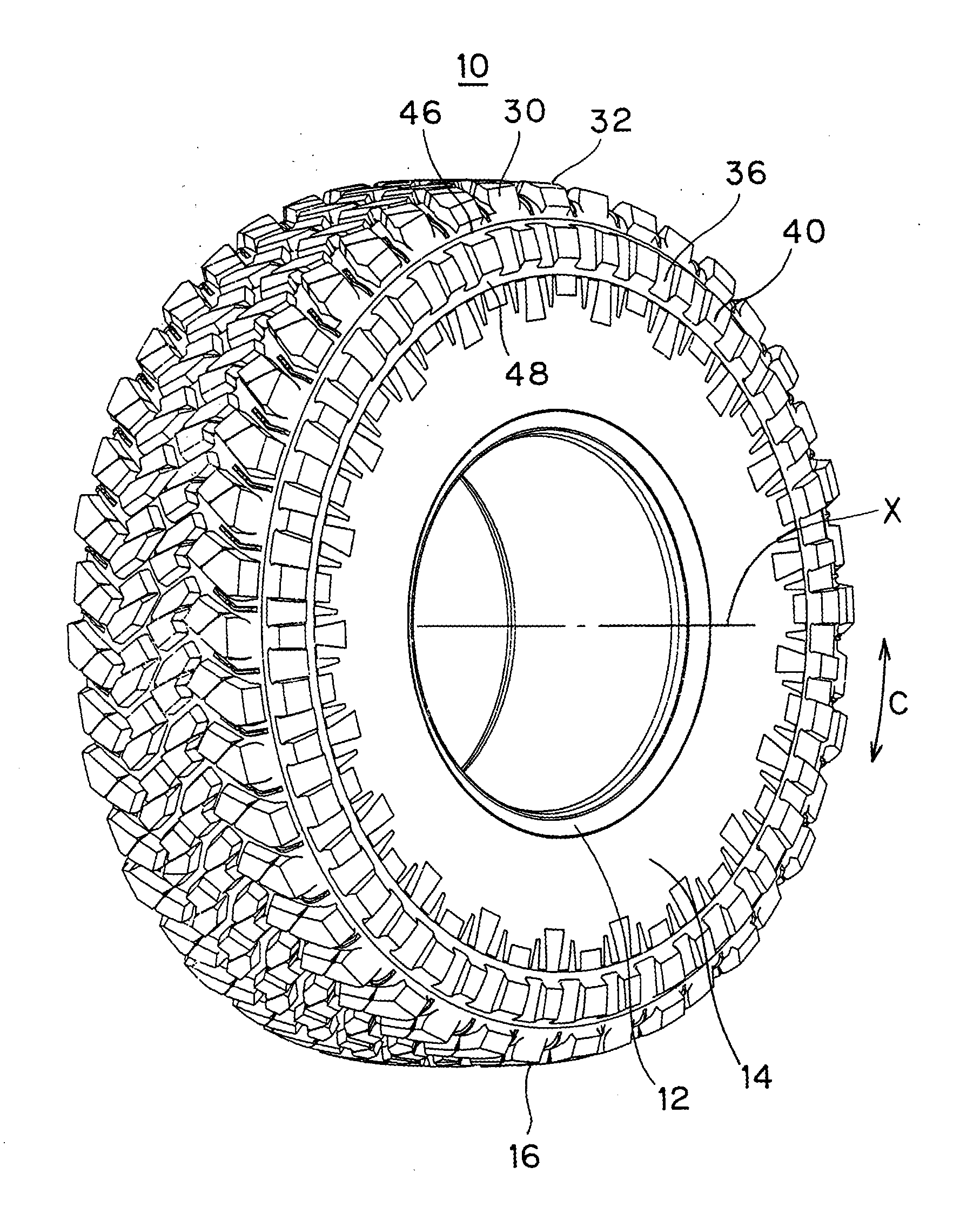
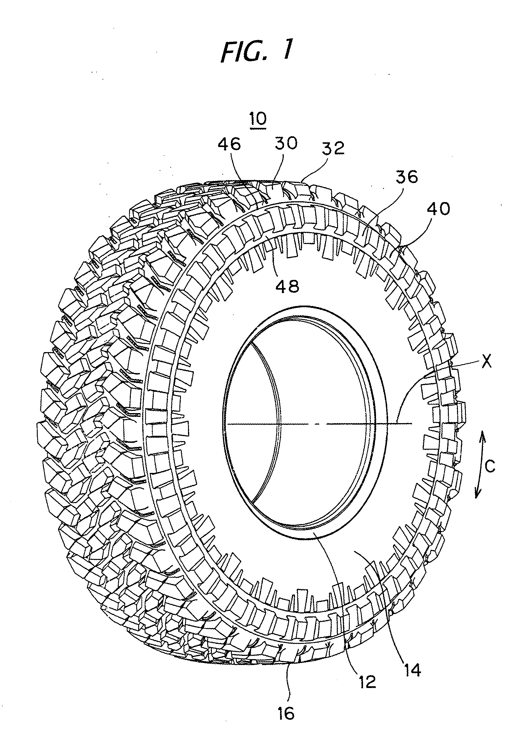
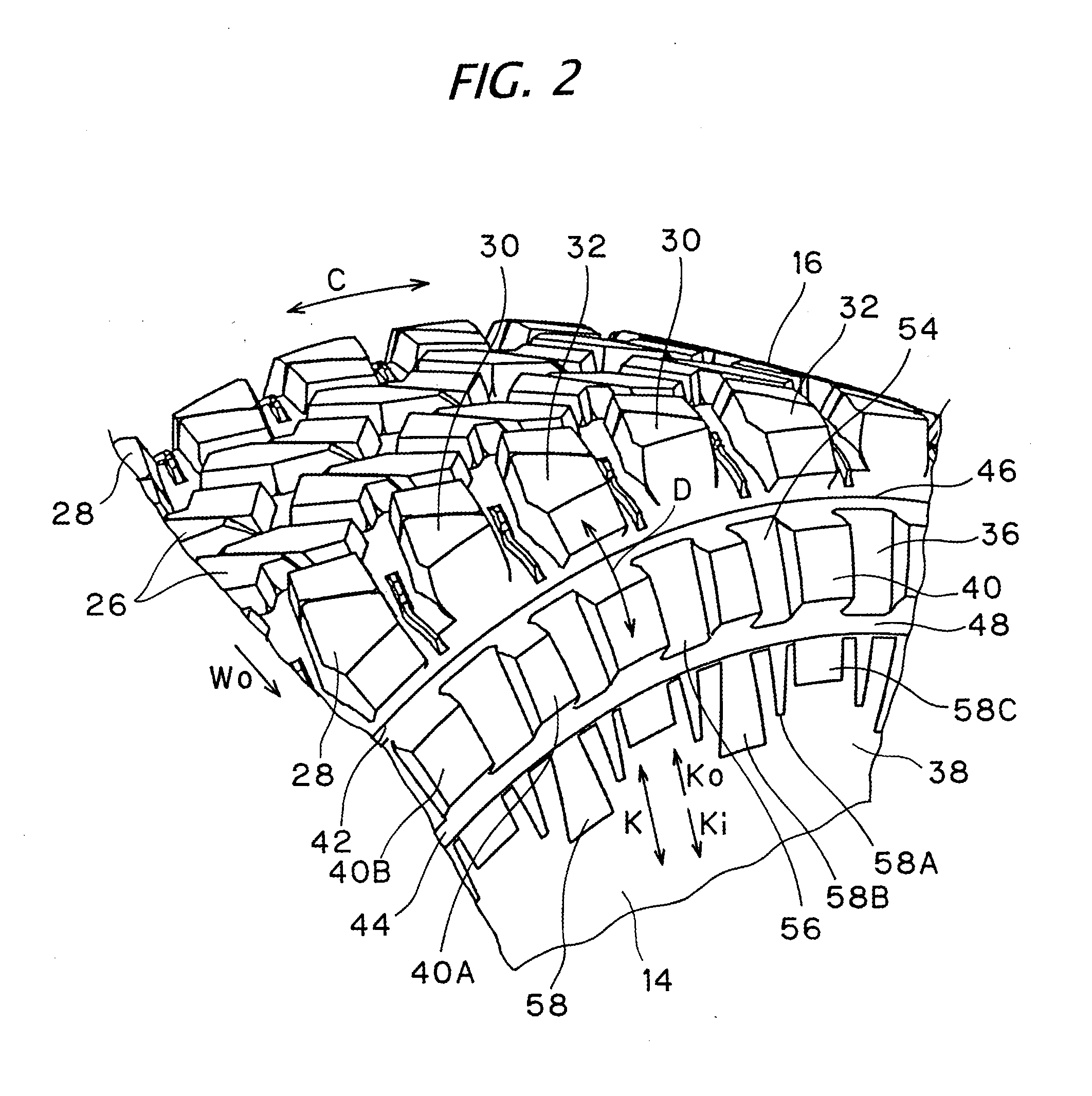
[0021]In an embodiment of the pneumatic radial tire, the inner thin wall part may be arranged on a central part in the radial direction, of a region sandwiched between the inner radius height and the maximum width position. In another embodiment, the outer thin wall part and the inner thin wall part may be respectively formed by an outer circumferential groove along the outer circumferential edge of the annular region and an inner circumferential groove along the inner circumferential edge of the annular region, on outer face of the tire, and the outer and inner circumferential groove may be recessed as compared to a base surface of the annular region. In this case, the base surface of the annular region may be provided as a table-top face of a table-shaped area raised from a bottom that appears as a straight line connecting groove bottoms of the outer circumferential groove and the inner circumferential groove in a cross-section of the tire, and each of the projections may protrude...


PUM


Abstract

A pneumatic radial tire includes three or less steel belt layers, wherein a first block and a second block extending in an outer side than the first block are alternately provided in a tire circumferential direction on a ground edge region of a tread part. An annular region extending in a circumferential direction is provided on the outer surface of an outer side than a maximum width position in a side wall part, and plural projections are provided side by side on the annular region. An outer thin wall part continuing along an outer circumferential edge of the annular region and an inner thin wall part continuing along an inner circumferential edge of the annular region are provided, and the outer thin wall part is arranged adjacent to an inner radius height and inside of the inner radius height.

Description

CROSS-REFERENCE TO RELATED APPLICATIONS[0001]This application is based upon and claims the benefit of priority from the prior Japanese Patent Application No. 2011-266959, filed on Dec. 6, 2011; the entire contents of which are incorporated herein by reference.BACKGROUND[0002]1. Technical Field[0003]The disclosure relates to a pneumatic radial tire.[0004]2. Related Art[0005]In a pneumatic radial tire for the purpose of running rough road, a technique of providing plural projections arranged along a tire circumferential direction on a side wall part is conventionally known (for example, see JP-A-2010-188975). The projections have a function to generate traction by shear resistance when a tire sank in a muddy ground, and are provided for the purpose of securing driving performance on a muddy ground. Furthermore, it is known that external damage resistance performance during running rough road is improved by the projections.[0006]Off-road races include a race of running not only muddy g...

Claims


Application Information

Patent Timeline
Patent Type & Authority Applications(United States)
IPC IPC(8): B60C11/11
CPCB60C13/02B60C2200/14B60C2011/1361B60C11/11B60C9/2006
Inventor OHARA, MASAAKI
Owner TOYO TIRE & RUBBER CO LTD
Why Eureka
Try Eureka