Sole structure for a shoe

Active Publication Date: 2009-10-01
MIZUNO CORPORATION
View PDF15 Cites 49 Cited by
  • Summary
  • Abstract
  • Description
  • Claims
  • Application Information

AI Technical Summary

Benefits of technology

[0046]In such a case, at the time of a shoe strike onto the ground, the cleat contacts the ground first and thereafter the first and second C-shaped portions contact the ground to compressively deform into a more flattened shape. As a result, the amount of protrusion of the cleat from the lower surface of each of the C-shaped portions increases to raise a grip of the cleat. On the other hand, when each of the C-shaped portions leaves the ground, the lower surface of each of the C-shaped portions returns to its original position. As a result, the amount of protrusion of the cleat fro

Problems solved by technology

However, in this case, since the adjacent band-shaped wavy corrugated sheets are coupled to each other by the connections, the amount of compressive deformation of the wavy corrugated portions of the band-shaped wavy corrugated sheets is restricted.
However, in this case, since the upwardly convex surface of the wavy corrugated plate is fixedly attached to

Method used


Image

  • Sole structure for a shoe
  • Sole structure for a shoe
  • Sole structure for a shoe

Examples


first embodiment

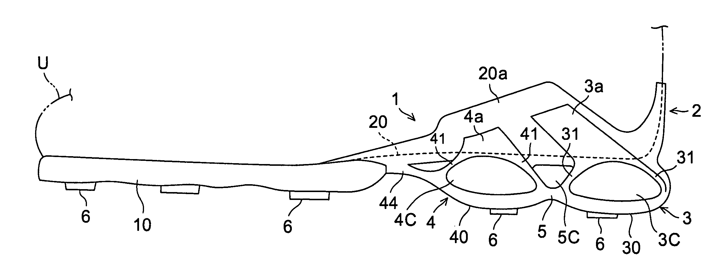
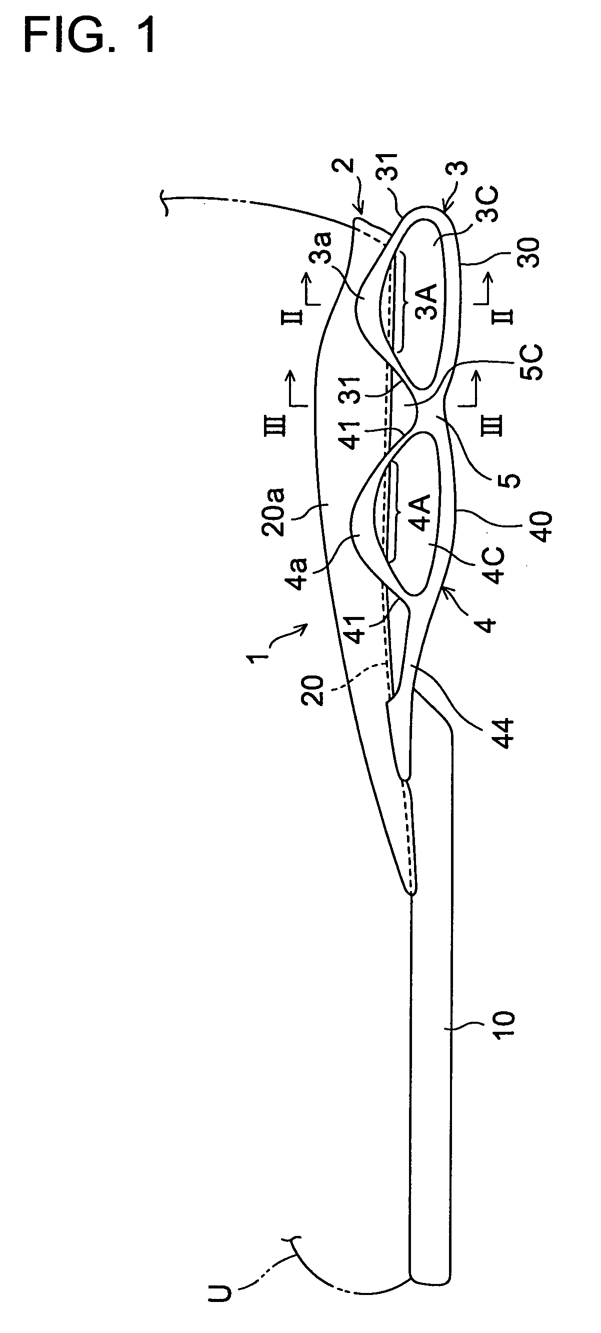
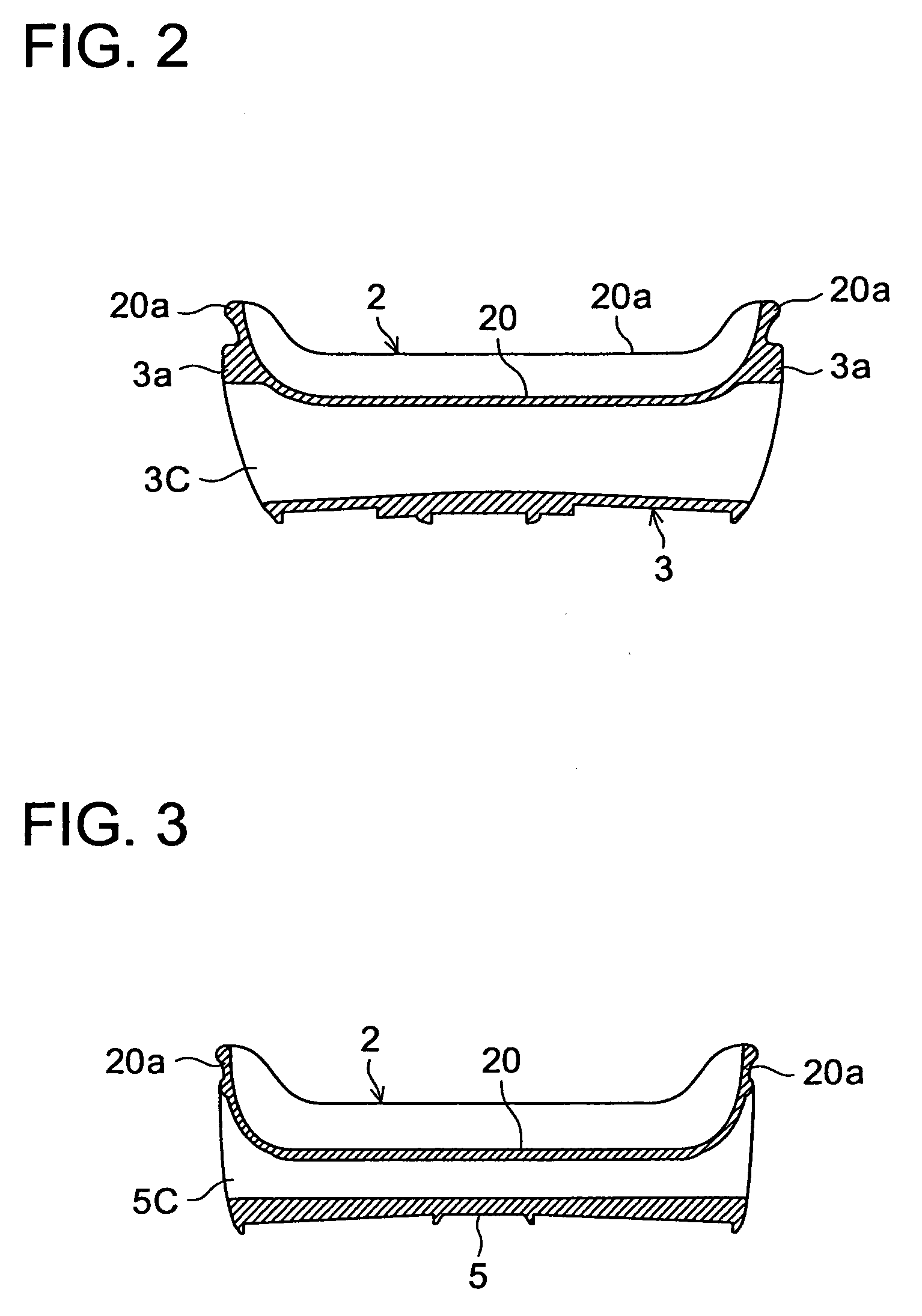
[0069]Referring now to the drawings, FIGS. 1 to 3 show a sole structure or a sole assembly for a shoe according to the present invention. In these drawings, like reference numbers indicate identical or functionally similar elements. Here, a spike-less golf shoe is exemplified.

[0070]As shown in FIG. 1, a sole structure 1 comprises an upper plate 2 having at least a heel region, disposed on an upper side of the sole structure 1, and having a lower portion of an upper U of the shoe fixedly attached thereto, a first C-shaped portion 3 and a second C-shaped portion 4 each having a longitudinally flat, generally C-shape with an upwardly opening portion 3A, 4A, disposed alongside in the longitudinal direction under the upper plate 2, each opening end of the upwardly opening portions 3A, 4A being directly fixed to the upper plate 2, and a connecting portion 5 interposed between the first and second C-shaped portions 3, 4 and connecting the first and second C-shaped portions 3, 4.

[0071]The u...

third embodiment

[0092]In this third embodiment, positions of the upwardly opening end portions of the first and second C-shaped portions 3, 4 are spaced equally along the upper plate 2 as shown in a distance 1 of FIG. 6A. That is, the distances 1 between the adjacent connecting parts of the C-shaped portions 3, 4 with the upper plate 2 are spaced equally along the upper plate 2. At the time of a shoe strike onto the ground, a thrust from the ground is equally distributed and transmitted to the upper plate 2 through these four connecting parts. Thereby, an undesirable thrust to the shoe wearer's foot can be further decreased.

[0093]FIGS. 7A and 7B show a sole structure according to a fourth embodiment of the present invention. In these drawings, the same numbers as those in the first embodiment indicate identical or functionally similar elements.

[0094]The fourth embodiment differs from the first to third embodiments in that the connecting portion 5 is located above the longitudinal line L connecting ...

fourth embodiment

[0095]In the fourth embodiment, since the connecting portion 5 is located above the longitudinal line L, at the time of a compressive deformation of each of the C-shaped portions 3, 4, the compressive deformation of an upper portion above the longitudinal line L is restrained, and at the same time the compressive deformation of a lower portion below the longitudinal line L is promoted. Also, since the connecting portion 5 has an upwardly convexly crooked shape, at the time of the compressive deformation of each of the C-shaped portions 3, 4, the connecting portion 5 deforms into a more crooked shape as shown in FIG. 7B. Thereby, the amount of compressive deformation of the entire sole structure can be further increased and the cushioning properties can thus be improved.

[0096]FIGS. 8A and 8B show a sole structure according to a fifth embodiment of the present invention. In these drawings, the same numbers as those in the first embodiment indicate identical or functionally similar ele...


PUM


Abstract

A sole structure 1 for a shoe comprises an upper plate 2 having a heel region and disposed on the upper side of the structure 1, a first C-shaped portion 3 and a second C-shaped portion 4 each having a longitudinally flat, generally C-shape with an upwardly opening portion 3A, 4A, disposed alongside in the longitudinal direction under the upper plate 2, and each opening end of the upwardly opening portions 3A, 4A directly fixed to the upper plate 2, and a connecting portion 5 interposed between and connecting the first and second C-shaped portions 3. The C-shaped portions 3, 4 are formed of downwardly convexly curved surfaces 30, 40 and diagonally upwardly convexly curved surfaces 31, 41, respectively, which extend diagonally upwardly from the downwardly convexly curved surfaces 30, 40 toward the upper plate 2.

Description

BACKGROUND OF THE INVENTION[0001]The present invention relates generally to a sole structure for a shoe, and more particularly, to an improved sole structure for facilitating a compressive deformation to enhance cushioning properties and for reducing a thrust from the ground.[0002]We proposed a sole structure such as shown in Japanese patent application laying-open publication No. 11-235202 (JP 11-235202). The sole structure is comprised of a plurality of band-shaped wavy corrugated sheets arranged side by side and connections that connect the adjacent wavy corrugated sheets with each other.[0003]Also, Japanese patent application laying-open publication No. 2003-339405 (JP 2003-339405) shows a sole structure composed of an upper plate and a lower plate that are disposed oppositely to each other via a void in the upper and lower direction, and a wavy corrugated plate that is interposed between the upper plate and the lower plate and that has an upwardly convex surface fixedly attache...

Claims


Application Information

Patent Timeline
IPC IPC(8): A43B13/18A43C15/00A43B13/00
CPCA43B21/26A43B13/181A43B3/0063A43B7/144A43B13/183
Inventor KIMURA, TAKAYA
Owner MIZUNO CORPORATION
Why Eureka
Try Eureka