Heat exchanger

a technology of heat exchanger and heat exchange plate, which is applied in the direction of indirect heat exchanger, lighting and heating apparatus, laminated elements, etc., can solve the problems of heat exchange efficiency deterioration and deformation of heat transfer plates, and achieve the effect of improving the precision of joining to the inner casing and high precision

Inactive Publication Date: 2005-08-30
HONDA MOTOR CO LTD
View PDF21 Cites 45 Cited by
  • Summary
  • Abstract
  • Description
  • Claims
  • Application Information

AI Technical Summary

Benefits of technology

[0029]In accordance with this arrangement, since the radially inner edges of the first and second heat transfer plates are made perpendicular to the outer peripheral surface of the inner casing, not only is it possible to stack the first and second heat transfer plates with high precision, but also the precision of joining to the inner casing can be improved.

Problems solved by technology

Since the compressed air is forced toward the outside of the turn due to the centrifugal force caused by turning through 180°, it is difficult to make the compressed air, after it has turned, flow uniformly in the axially formed high pressure fluid passages within the heat exchanger, and there is a possibility that the heat exchange efficiency might deteriorate.
Furthermore, in a heat exchanger in which low pressure fluid passages and high pressure fluid passages are formed alternately between a large number of heat transfer plates stacked at predetermined intervals, a difference in pressure between a high pressure fluid flowing though the high pressure fluid passages and a low-pressure fluid flowing though the low pressure fluid passages generates a load to push the heat transfer plates toward the low pressure fluid passages, and there is a possibility that deformation will be caused between the heat transfer plates unless a large number of ridges for supporting the load are formed within the low-pressure fluid.

Method used


Image

  • Heat exchanger
  • Heat exchanger
  • Heat exchanger

Examples


first embodiment

[0034]the present invention is explained below by reference to FIG. 1 to FIG. 7.

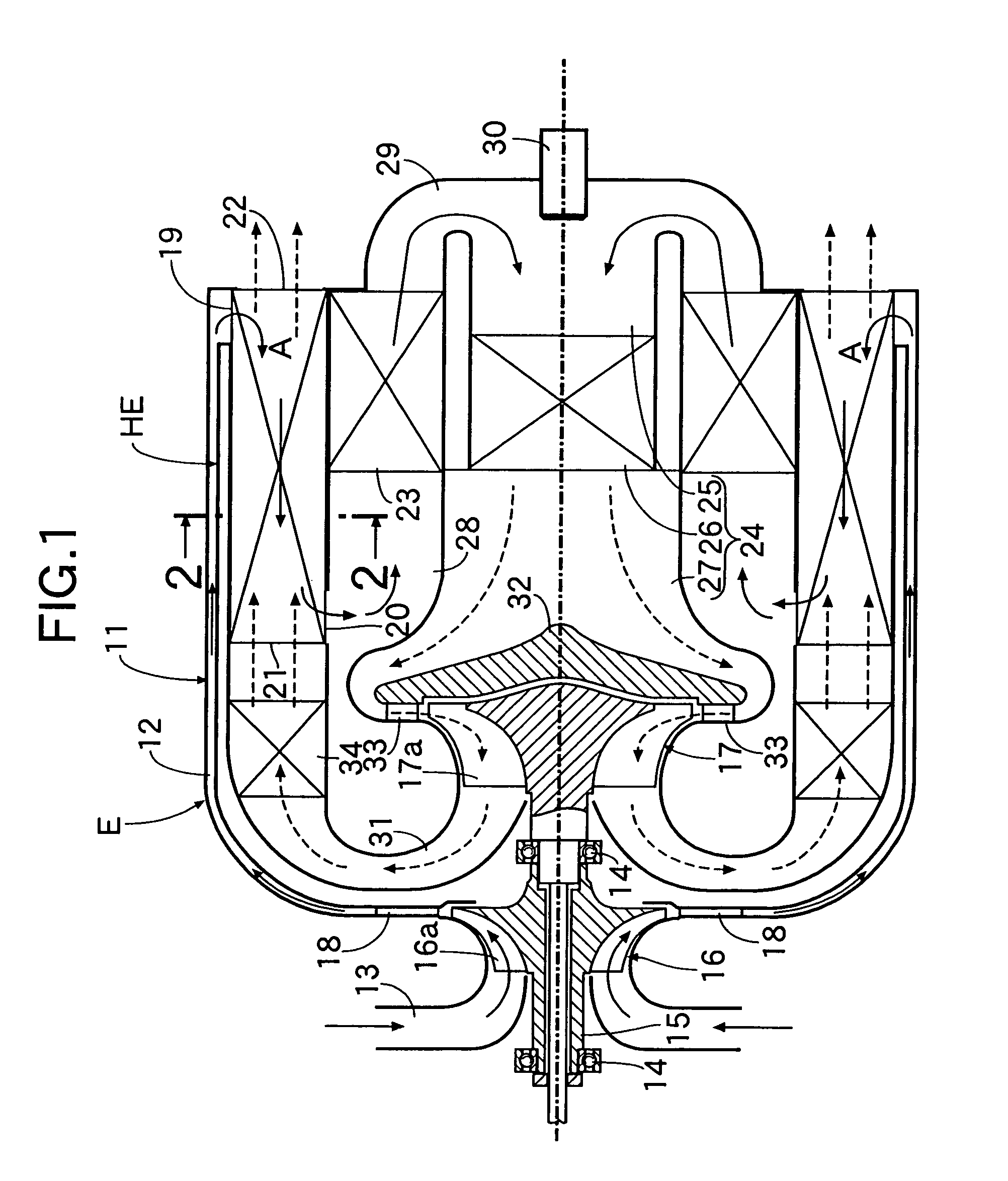
[0035]Referring to FIG. 1, an outline explanation is firstly given of the structure of a gas turbine engine E in which a heat-transfer type heat exchanger HE of the present embodiment is mounted.

[0036]The gas turbine engine E includes a substantially cylindrical engine casing 11. Formed on the outer periphery of the engine casing 11 is a first compressed air passage 12, to the upstream side of which is connected an intake passage 13 communicating with an air cleaner and a silencer (not illustrated).

[0037]A centrifugal compressor wheel 16 and a centrifugal turbine wheel 17 are coaxially and adjacently fixed on a rotating shaft 15 running through the center of the intake passage 13 and supported by a pair of bearings 14 and 14. A plurality of compressor blades 16a are radially formed on the outer periphery of the compressor wheel 16 and face the intake passage 13, and a plurality of compressor diffusers 18...

second embodiment

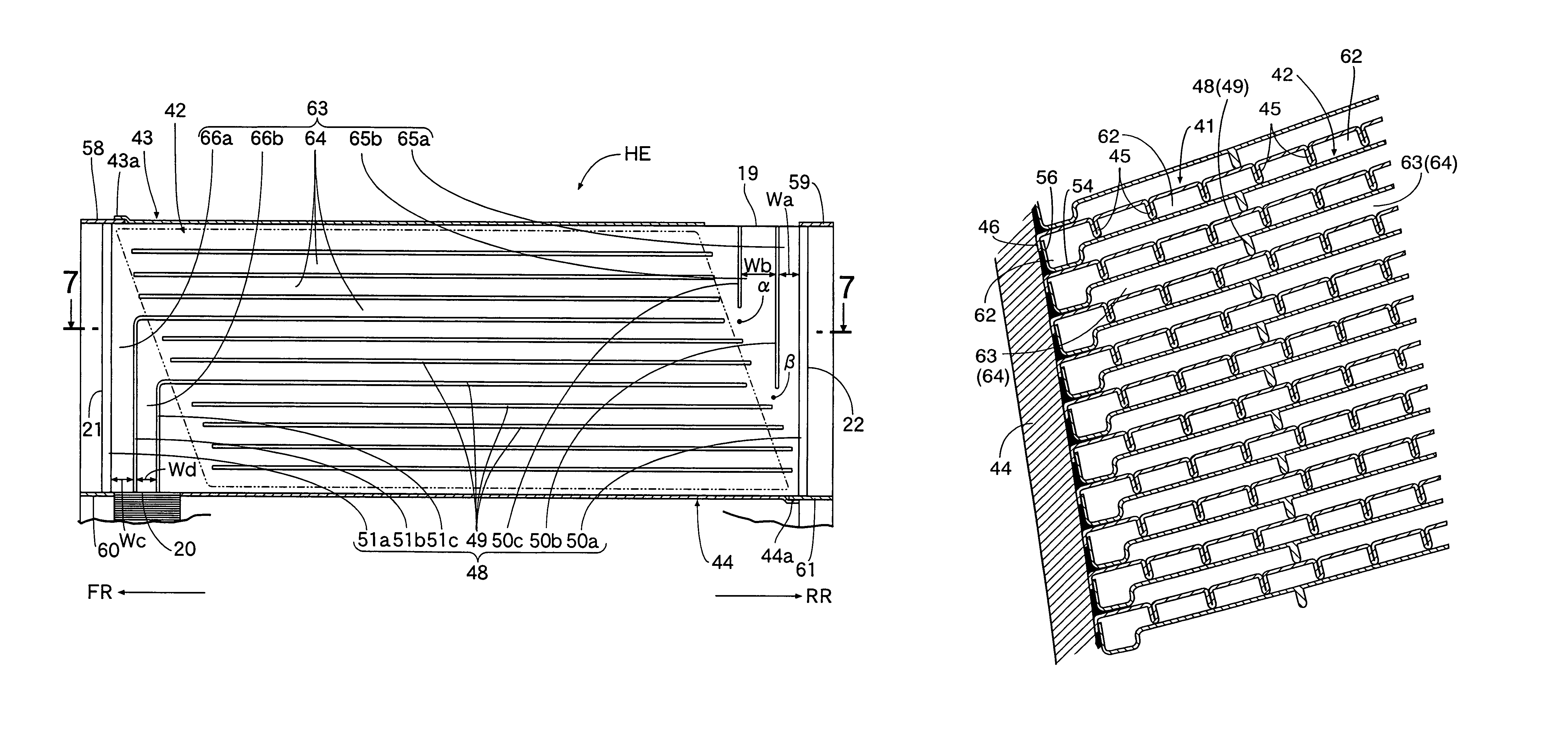
[0069]FIG. 8 and FIG. 9 show the present invention, FIG. 8 is a perspective view of a heat exchanger, and FIG. 9 is a view from arrow 9 in FIG. 8.

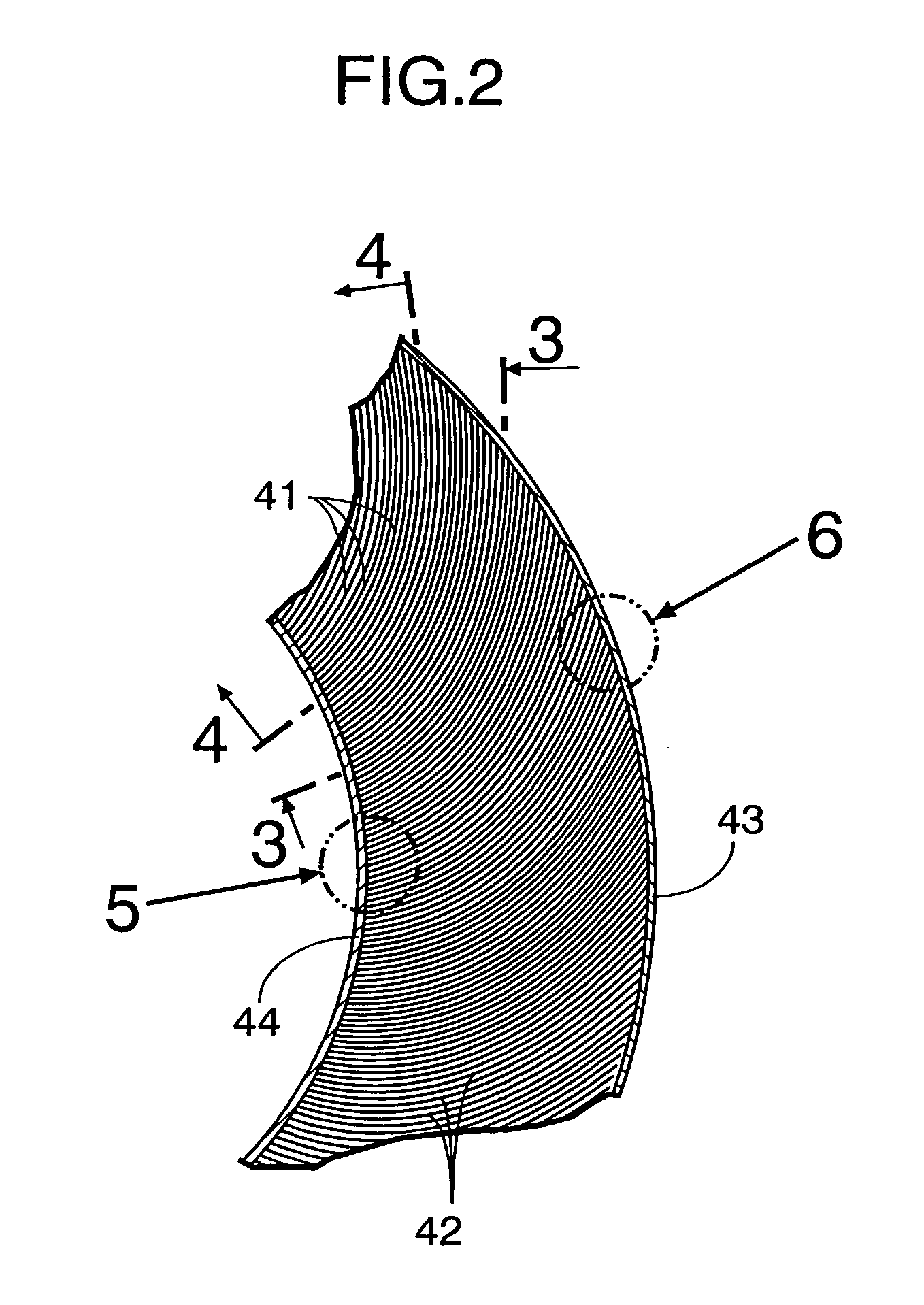
[0070]Whereas the heat exchanger HE of the above-mentioned first embodiment is made in an annular form, a heat exchanger HE of the second embodiment is made in a rectangular parallelepiped form. Although the structures of first heat transfer plates 41 and second heat transfer plates 42 are substantially the same as those in the first embodiment, whereas the first and second heat transfer plates 41 and 42 of the first embodiment are involutely curved, the first and second heat transfer plates 41 and 42 of the second embodiment are made in the form of flat plates.

[0071]One edge of the alternately stacked first and second heat transfer plates 41 and 42 is joined to an end plate 43′ corresponding to the outer casing 43, and the other edge thereof is joined to an end plate 44′ corresponding to the inner casing 44. Furthermore, a pair of side pl...


PUM


Abstract

A heat exchanger is provided in which second heat transfer plates (42) and first heat transfer plates (not illustrated) are alternately superimposed so as to form high pressure fluid passages (63) and low pressure fluid passages (not illustrated). The high pressure fluid passages (63) include inlet fluid passages (65a, 65b) defined by inlet ridges (50a to 50c) extending from a compressed air inlet (19), and main fluid passages (64) defined by a plurality of main ridges (49) extending parallel to each other in the longitudinal direction of the second heat transfer plates (42) so as to be perpendicular to the inlet fluid passages (65a, 65b). The two inlet fluid passages (65a, 65b) have different widths (Wa, Wb), and gaps (α, β) are formed between the downstream ends of the two inlet ridges (50b, 50c) and the upstream ends of the main ridges (49). A high pressure fluid can thereby be uniformly distributed into the main fluid passages (64) connected to the inlet fluid passages (65a, 65b) of the high pressure fluid passages (63) of the heat exchanger.

Description

FIELD OF THE INVENTION[0001]The present invention relates to a heat exchanger having first heat transfer plates and second heat transfer plates alternately superimposed so as to alternately form low pressure fluid passages and high pressure fluid passages between the two heat transfer plates.BACKGROUND ART[0002]A heat exchanger having fluid passages for a high temperature fluid to flow and fluid passages for a low temperature fluid to flow, the fluid passages being alternately disposed so that heat is exchanged between the high temperature fluid and the low temperature fluid, is already known from, for example, Japanese Utility Model Registration Application Laid-open No. 3-79082, Published Japanese Translation No. 5-506918 of a PCT Application, and U.S. Pat. No. 3,831,374.[0003]In the Japanese Utility Model Registration Application Laid-open No. 3-79082, a large number of gap-maintaining parts are projectingly provided by bending paper partitions at predetermined intervals, the gap...

Claims


Application Information

Patent Timeline
Patent Type & Authority Patents(United States)
IPC IPC(8): F28D9/00
CPCF28D9/0018F28D9/0037Y10S165/358F28F2250/108
Inventor TSUNODA, TADASHIKIMURA, HIDEMIYAMAMURA, HIDEICHIOGAWA, TETSUYA
Owner HONDA MOTOR CO LTD
Why Eureka
Try Eureka