Anti-icing wind power blade and blade deicing and heating method

a technology blades, applied in wind motors, climate sustainability, final product manufacture, etc., can solve the problems of wind power blades that are very easily frozen in winter, wind power blades that are difficult to remove ice, and wind power blades that are difficult to maintain. the effect of preventing ice accumulation

Active Publication Date: 2019-12-10
ZHUZHOU TIMES NEW MATERIALS TECH
View PDF18 Cites 4 Cited by
  • Summary
  • Abstract
  • Description
  • Claims
  • Application Information

AI Technical Summary

Benefits of technology

[0015]The current invention comprises an air heating system and an electric heating system, wherein these two systems are independent from each other and do not interfere with each other. However, when the electric heating system malfunctions, the air heating system automatically starts the choke plate II and heats the front edge.
[0016]The heating unit of the electric heating system is disposed on the outer surface of the front edge of the blade and is responsible for preventing and removing ice. Since the heating unit of the electric heating system is disposed on the outer surface of the blade, when the heating unit of the electric heating system malfunctions, repair is difficult. At this time, the choke plate II is automatically opened, and the choke plate Ill can be manually or automatically opened, and in this way, the heated air can enter the front edge, and a certain degree of anti-icing can be achieved.
[0017]The air heating system comprises the air heating system at the blade root, which sends the heated air into the guide duct at the specified position. The heating element is mainly made of PTC material. When the temperature increases, the power of such material also increases. When the temperature reaches certain value, the power of such material is gradually stable. As a result, such heating element is relatively safe.
[0018]More specifically, the wind blower brings cold air into the heating device, the cold air is heated by the heating device, and the heated air is then conducted to the specified position of the back edge of the blade via the guide duct, where there is the choke plate I at this specified position, so that the heated air can only blow toward the blade tip, and be recirculated back to the blade root through the middle of the web plate and be conducted into the next cycle by the wind blower, so that the closed cycle of “blade root-blade tip-blade root” is formed and the efficiency of heat utilization is increased.

Problems solved by technology

As a result, during the operation of the wind power generator, the wind turbine blades will experience the tests of all kinds of severe environments.
Especially at wet and cold highlands, the wind turbine blades are very easily frozen in winter.
After the blade freezes, the blade has a heavier load and its aerodynamic performance becomes worse, which has great influence on the safety and the power of the generator.
In severe cases, it can cause a long stall of the generator, which results in damage to the blades and thus reduces its working life.
However, it does not disclose the detailed distribution of the pipelines for the heated air in the blade.
However, the resistors can easily be struck by lightning.
In addition, malfunction of the resistors is also difficult to repair.

Method used


Image

  • Anti-icing wind power blade and blade deicing and heating method

Examples


embodiment 1

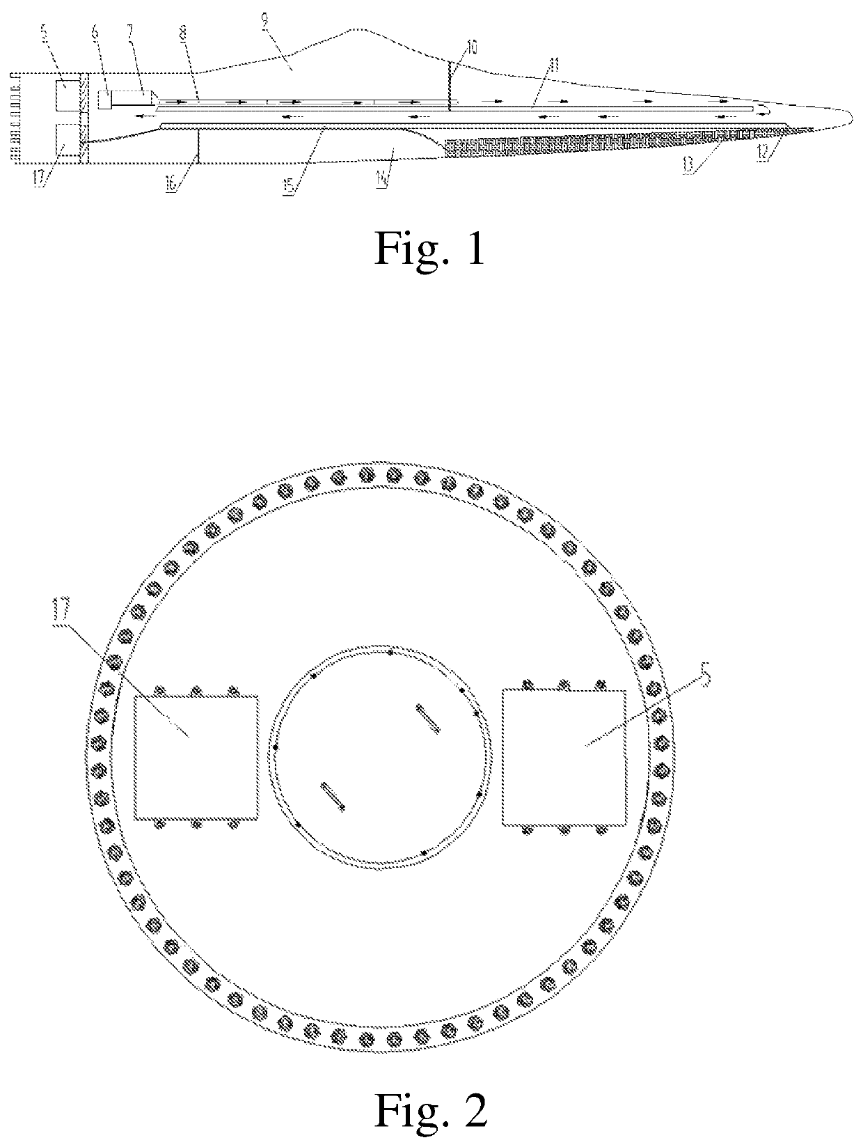
[0023]According to FIG. 1 to FIG. 2, an anti-icing wind power blade, containing an air heating control cabinet 5, an air heating device, an electric heating control cabinet 17, an electric heating element 13, front and back edge web plate 15, 11, the wind turbine blade is divided into a front edge and a back edge 14, 9 by a front edge web plate and a back edge web plate 15, 11, wherein the electric heating element is disposed on the outer surface of the front edge of the blade 14, and the air heating system is disposed at the blade root. A choke plate II 12 is located between the blade tip of the front edge 14 and the front edge web plate 15, a choke plate III 16 is located between the blade root of the front edge 14 and the front edge web plate 15. A guide duct 8 is provided in the back edge web plate 11. The guide duct is fixed on the back edge web plate 11 with hand-layed glass fabric, wherein the guide duct is made of fiberglass. A choke plate 110 is located between the two ends...


PUM


Abstract

An anti-icing wind power blade, consisted of a wind turbine blade, wherein the wind turbine blade is provided with an anti-icing heating device, and wherein the anti-icing heating device consists of an air heating system and an electric heating system, wherein the two systems are independent from each other, without mutual interference, and heat the wind turbine blade separately or simultaneously. The air heating system and the electric heating system are both located inside the wind turbine blade, wherein the air heating system comprises an air heating control cabinet and an air heating device, and the electric heating system comprises an electric heating control cabinet and an electric heating element, the wind turbine blade is divided into a front edge and a back edge by a front edge web plate and a back edge web plate, wherein the air heating device is disposed in the back edge and the electric heating element is disposed on the outer surface of the front edge of the blade, and the air heating control cabinet and the electric heating control cabinet are disposed at the blade root. The current invention has an air heating system and an electric heating system. When the electric heating system malfunctions, the air heating system can automatically start and heat. As a result, the usage does not need to be stopped during repair, and the usage efficiency is increased, and is more appropriate for use in severe environment.

Description

TECHNICAL FIELD[0001]The current invention relates to components of a high power wind turbine generator system and its operation, and is especially related to a wind turbine blade of a high power wind turbine generator system and its heating method, wherein such wind turbine blade is provided with an anti-icing heating device in order to remove ice on the blade.TECHNICAL FIELD[0002]Wind power generation is a green energy generation method which has been drastically industrialized. With the fast development of the wind power generation, new markets with special environments for wind power have been developed. As a result, during the operation of the wind power generator, the wind turbine blades will experience the tests of all kinds of severe environments. Especially at wet and cold highlands, the wind turbine blades are very easily frozen in winter. After the blade freezes, the blade has a heavier load and its aerodynamic performance becomes worse, which has great influence on the s...

Claims


Application Information

Patent Timeline
Patent Type & Authority Patents(United States)
IPC IPC(8): F03D80/40F03D1/06F03D80/60
CPCF03D80/40F03D1/0675F03D80/60F03D1/06Y02E10/72Y02P70/50
Inventor ZHAO, JIANGANGPENG, CHAOYIYANG, WENTAOWANG, XIANXIE, MINGLIANGCHEN, LONGZENG, JINGCHENG
Owner ZHUZHOU TIMES NEW MATERIALS TECH
Why Eureka
Try Eureka