Submerged water desalination system with remote pump

a technology of desalination system and remote pump, which is applied in the direction of liquid fuel engines, machines/engines, and membranes, etc., can solve the problems of high cost, high power demand of ro units, and limited growth of saltwater (e.g. seawater) desalination, so as to reduce the pump output, reduce the cost, and discourage cavitation

Pending Publication Date: 2022-08-18
NATURAL OCEAN WELL CO
View PDF0 Cites 0 Cited by
  • Summary
  • Abstract
  • Description
  • Claims
  • Application Information

AI Technical Summary

Benefits of technology

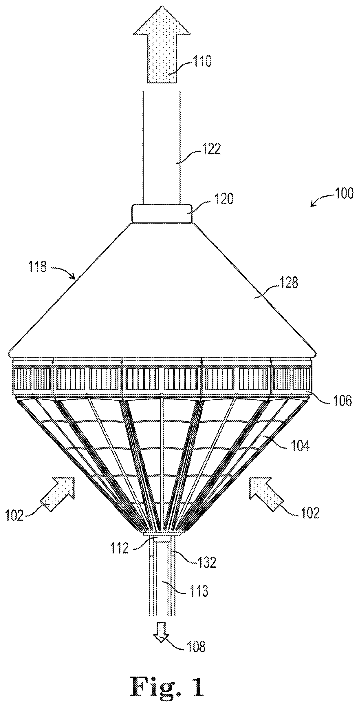
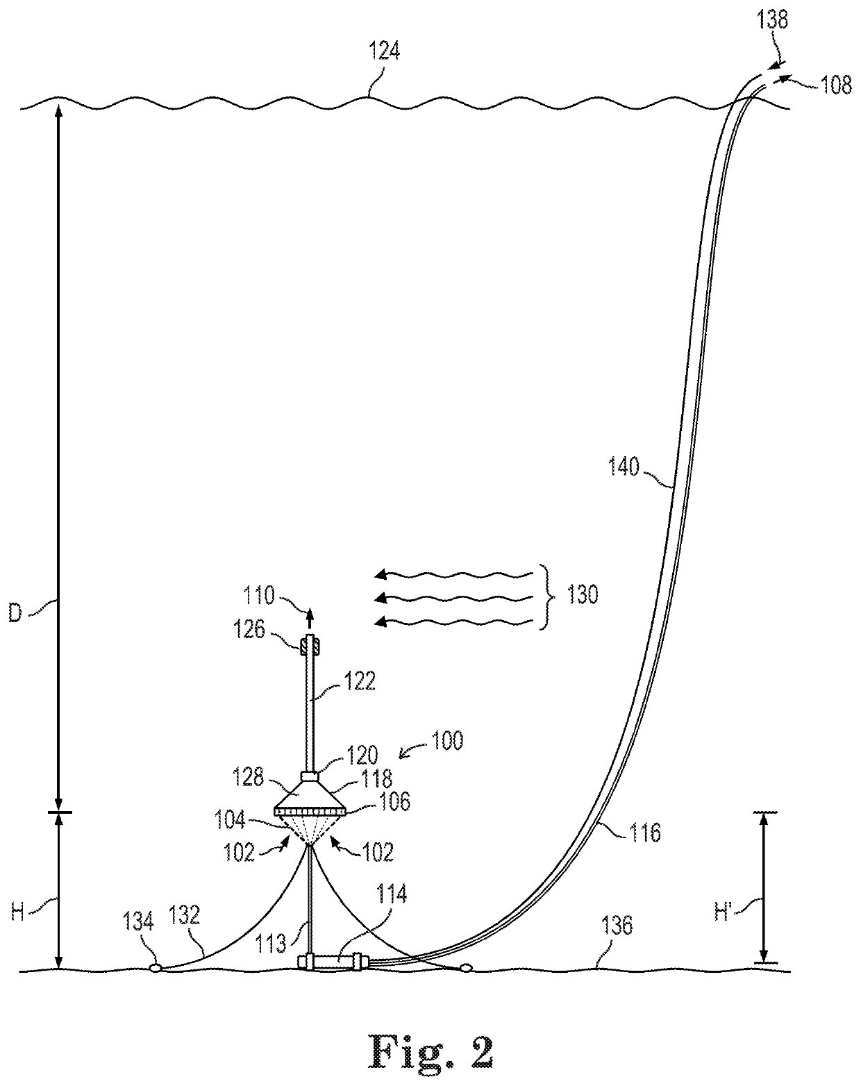
[0008]Compared to land-based water separation, a submerged water separation system can provide several important advantages. For example, submerged operation can significantly reduce pump power requirements, since hydrostatic pressure can provide much or all of the driving force required for desalination, and only desalinated water will need to be pumped onshore. A stream of product water may be produced using a pump located on the seawater inlet side of (viz., upstream from) the submerged water separation membranes. It is better however to provide the product water stream using a pump located on the outlet side of (viz., downstream from) the submerged water separation membranes, as doing so does not require as large a pump, and the pumped product water has much lower salinity and corrosion potential than the seawater entering the membranes. However, cavitation may take place at the inlet to such an outlet-side pump during pump startup or operation, causing damage to the pump impeller or to the nearby membrane. In a submerged water separation apparatus, cavitation can be especially troublesome. It can be difficult to detect cavitation in a submerged apparatus, difficult to intervene in timely fashion, and difficult to repair the apparatus should damage to the pump or membranes occur. The chosen components can be sized to avoid cavitation, but such an approach may lack adequate flexibility when operating conditions change, such as when the water separation membrane product water output drops due to upstream occlusions, membrane fouling, upstream mechanical failures or other causes. Cavitation due to low pump suction pressure at the product water outlet may be especially likely to occur in the presently disclosed apparatus, because the apparatus will preferably be operated in a normally non-preferred low product water recovery ratio mode in order to obtain a smaller than normal proportion of product water and a larger than normal and consequently diluted proportion of concentrate or brine, and in order to obtain other benefits discussed in more detail below.
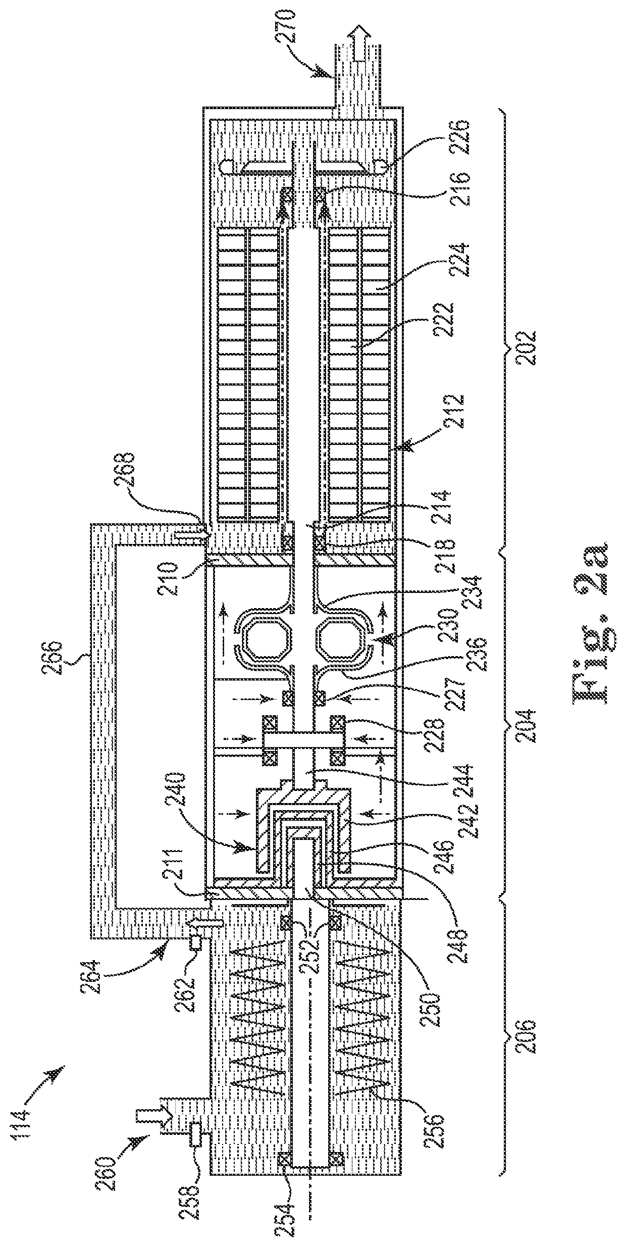
[0013]iv) an automatic control or coupling that reduces the pump output upon the occurrence or onset of suction side cavitation, and discourages or prevents cavitation over a range of product water flow rates from the membrane elements.
[0018]iv) automatically reducing the pump output upon the occurrence or onset of suction side cavitation, to discourage or prevent cavitation over a range of product water flow rates from the membrane elements.
[0019]The disclosed apparatus provides a submerged “Natural Ocean Well” that can provide desalinated water at reduced cost and with improved reliability compared to land-based water desalination systems, and with improved water desalination membrane and product water pump maintenance and lifetimes compared to existing submerged water desalination systems.

Problems solved by technology

The growth of saltwater (e.g., seawater) desalination has been limited by the relatively high cost of desalinated water.
This high cost is due in part to energy and capital expenses associated with current desalination systems.
In addition to such high pressures, onshore RO units suffer from high power demands, primarily for pressurizing the feedwater to membrane operating pressures, and for an onshore RO unit these power demands typically average about 13.5 kWh per thousand gallons of produced fresh water.
The seawater and the concentrated brine stream produced by a typical onshore RO unit have high corrosion potential and consequently require expensive components and equipment, including pressure vessels and conduits made from specialized alloys.
The highly-pressurized water flow also increases maintenance expenses.
Onshore RO units typically also require significant amounts of expensive seaside real estate.
Shore-based desalination has in addition been criticized for various environmental impacts, including entrainment of marine life in the intake water, greenhouse gas production associated with producing the energy required, discharge of a strong brine stream with the potential to harm marine life, the use of treatment chemicals that may enter the ocean, and onshore land use that is often expensive and may harm local ecosystems.
In general, submerged water desalination systems do not appear to have been placed in widespread use, due in part to factors such as the energy cost of pumping the desalinated water to the surface from great depth and the difficulty of maintaining component parts at depth.
However, cavitation may take place at the inlet to such an outlet-side pump during pump startup or operation, causing damage to the pump impeller or to the nearby membrane.
In a submerged water separation apparatus, cavitation can be especially troublesome.
It can be difficult to detect cavitation in a submerged apparatus, difficult to intervene in timely fashion, and difficult to repair the apparatus should damage to the pump or membranes occur.
The chosen components can be sized to avoid cavitation, but such an approach may lack adequate flexibility when operating conditions change, such as when the water separation membrane product water output drops due to upstream occlusions, membrane fouling, upstream mechanical failures or other causes.

Method used


Image

  • Submerged water desalination system with remote pump
  • Submerged water desalination system with remote pump
  • Submerged water desalination system with remote pump

Examples


Embodiment Construction

[0024]The recitation of a numerical range using endpoints includes all numbers subsumed within that range (e.g., 1 to 5 includes 1, 1.5, 2, 2.75, 3, 3.80, 4, 5, etc.).

[0025]The terms “a,”“an,”“the,”“at least one,” and “one or more” are used interchangeably. Thus, for example, an apparatus that contains “a” reverse osmosis membrane includes “one or more” such membranes.

[0026]The term “airlift” when used with respect to a pump refers to a device or method for pumping a liquid or slurry by injecting air (and preferably only by injecting air) into the liquid or slurry.

[0027]The term “automatic” when used with respect to control of a submerged pump means that the control operates in the vicinity of and based on conditions in such pump, and without requiring the sending of signals to or the receipt of signals from a surface vessel, platform, or other non-submerged equipment.

[0028]The term “brine” refers to an aqueous solution containing a materially greater sodium chloride concentration t...


PUM

PropertyMeasurementUnit
heightaaaaaaaaaa
heightaaaaaaaaaa
heightaaaaaaaaaa

Abstract

A submersible water desalination apparatus includes a plurality of water separation membrane elements that when supplied with salinated water under pressure at a first depth will produce at least partially desalinated product water and concentrate or brine; a product water collector that receives product water from the membrane elements; and a permeate conduit that transports product water from the collector downwardly to a motorized submersible pump remotely located from the membrane elements and collector at a second depth greater than the first depth. The second depth is sufficiently greater than the first depth so that the height of a standing column of product water in the product water collector and permeate conduit between the membrane elements and the suction side of the pump maintains a net positive suction head that prevents inlet side cavitation during pump startup and operation.

Description

CROSS-REFERENCE TO RELATED APPLICATIONS[0001]The present application is a continuation under 35 U.S.C. § 111(a) of International Patent Application No. PCT / US2020 / 058573, filed on Nov. 2, 2020, which claims priority to U.S. Provisional Patent Application No. 62 / 929,564, filed on Nov. 1, 2019, the disclosures of which are incorporated by reference herein.TECHNICAL FIELD[0002]This invention relates to water desalination.BACKGROUND ART[0003]The growth of saltwater (e.g., seawater) desalination has been limited by the relatively high cost of desalinated water. This high cost is due in part to energy and capital expenses associated with current desalination systems. Such systems typically employ an onshore facility containing reverse osmosis (RO) desalination or other water separation membranes contained in high-pressure corrosion-resistant housings and supplied with seawater from a submerged offshore intake system. Very high pressures typically are required to drive water through the me...

Claims


Application Information

Patent Timeline
Patent Type & Authority Applications(United States)
IPC IPC(8): C02F1/44B01D61/08B01D61/10
CPCC02F1/441C02F2103/08B01D61/10B01D61/08B01D61/025B01D2313/06B01D2315/06C02F2201/007C02F2201/009C02F2303/14C02F2201/008Y02W10/37Y02A20/212Y02A20/131B01D2313/243B01D61/12B01D2313/20B01D2313/18B01D2313/54B01D2313/56B01D2311/08B01D2313/36B01D61/04B01D65/003B01D2313/125B01D2313/44B01D2317/04C02F2201/004C02F2201/006F04D29/588C02F2209/03C02F2209/06C02F2209/22C02F2209/40F03G7/05C02F2201/002B01D2313/13B01D2319/04C02F2209/05B01D61/026B01D61/06B01D2313/365B01D2313/367B01D2313/206
Inventor BERGSTROM, ROBERT A.PORTER, MICHAEL M.
Owner NATURAL OCEAN WELL CO
Why Eureka
Try Eureka