White light-emitting device with improved doping

a technology of light-emitting devices and diodes, which is applied in the direction of discharge tubes luminescnet screens, other domestic articles, natural mineral layered products, etc., can solve the problems of difficult control, low intensity of red components of emission spectrum, and only about 30% of original white light, etc., to improve the color purity of red components, improve the intensity of red components, and reduce the power requirement of red pixels

Inactive Publication Date: 2005-04-05
GLOBAL OLED TECH
View PDF6 Cites 152 Cited by
  • Summary
  • Abstract
  • Description
  • Claims
  • Application Information

AI Technical Summary

Benefits of technology

The following are features and advantages of the present invention.
Full-color displays using white OLEDs constructed according to the present invention together with suitable color filters have an improved intensity of the red component.
Full-color displays using white OLEDs constructed according to the present invention together with suitable color filters have a reduced power requirement for the red pixels.
Full-color displays using white OLEDs constructed according to the present invention together with suitable color filters have an improved color purity of the red component.
The OLEDs constructed according to the present invention have high operational stability.
OLED devices constructed according to the present invention can be produced consistently and with high reproducibility to provide high efficiency, low drive voltage, and good stability.

Problems solved by technology

These concentrations are difficult to control during large-scale manufacturing.
However, the color filters each transmit only about 30% of the original white light.
A problem in the application of white OLEDs, when used with color filters, is that the intensity of the red component of the emission spectrum is frequently lower than desired.
Therefore, passing the white light from the OLED through the red filter provides red light with a lower efficiency than desired, and the power that is required to provide a desired intensity of red light is higher than desired.

Method used


Image

  • White light-emitting device with improved doping
  • White light-emitting device with improved doping
  • White light-emitting device with improved doping

Examples


examples 2-4

The OLEDs of Examples 2-4 were constructed similarly to that of Comparative Example 1, except that the HTL was codoped with 2% of rubrene and with DCJTB as a red dopant, the percentages being indicated in Table 1a. Also reported in Table Ia is the performance of the devices at a current density of 20 mA / cm2 in terms of drive voltage and photometric parameters (luminous yield and CIE coordinates) with no color filter. The same photometric parameters are reported in Table Ib for each OLED with a red, green, or blue color filter.

TABLE IaComposition and performance parameters of the OLEDsof Examples 1-4 without color filters and at a currentdensity of 20 mA / cm2Column 2 indicates the percentage of the red dopant,DCJTB, in the hole-transporting layer; Column 3reports the drive voltage; Column 4 reports theluminous yield; and Column 5 reports the CIE coordinates%VdriveYieldCIEx,ExampleDCJTB(V)(cd / A)CIEy106.74.00.34, 0.4120.16.84.30.37, 0.4430.256.94.50.39, 0.4640.56.84.60.41, 0.47

TABLE Ib...

examples 5-9

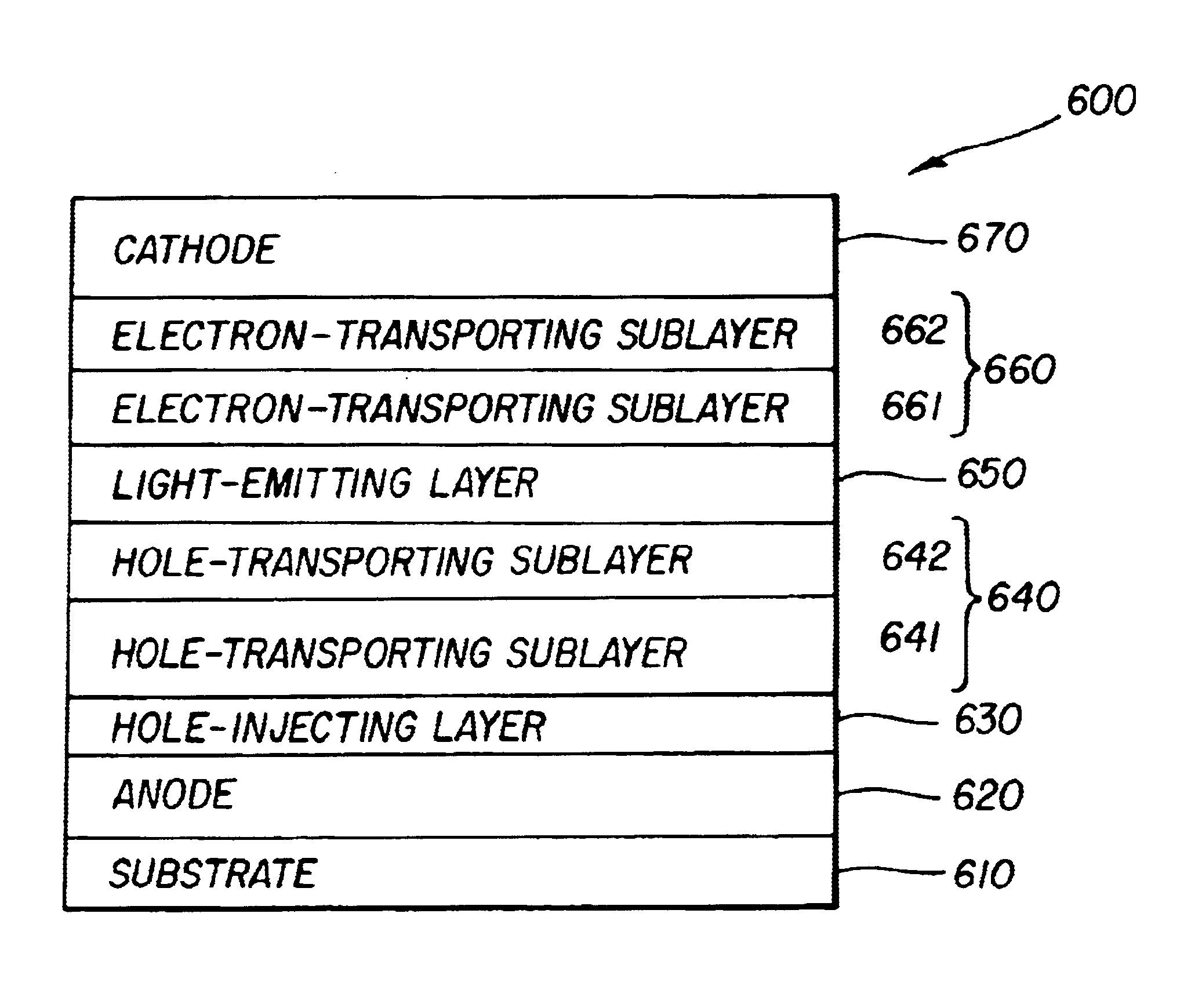
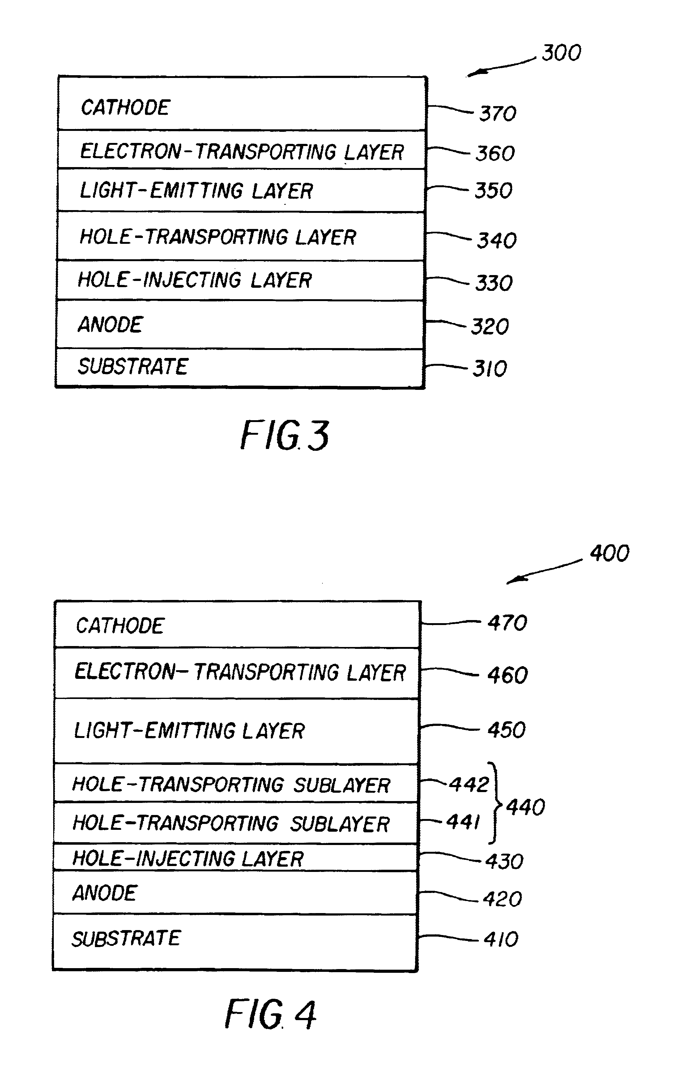
The OLEDs of Examples 6 to 9 were prepared following the structure of OLED 400 as shown in FIG. 4. The hole-transporting layer included a 130 nm thick sublayer of undoped NPB (441) and a 20 nm thick sublayer (442) of NPB codoped with 2% of rubrene as a yellow dopant and various percentages of DCJTB as a red dopant. The blue light-emitting layer (450) was a 25 nm thick layer of TBADN as host doped with 5% BDTAPVB as a blue dopant. The electron-transporting layer (460) was 35 nm of Alq. The OLED of Comparative Example 5 was similar, except that sublayer 442 contained no DCJTB. With respect to the substrate (410), anode (420), hole-injection layer (430), and cathode (470), the OLEDs of Examples 5-9 were the same as for the OLED of Comparative Example 1.

Tables IIa and IIb indicate the percentages of DCJTB and the performance of these devices at 20 mA / cm2. Included is the power consumption of the simulated display panel operated at the D60 white point. The luminous yield without a filter...

examples 10-13

The OLEDs of Comparative Example 10 and Examples 11 to 13 had the structure shown in FIG. 3 and were prepared similarly to the devices of Examples 1 to 4 except that the red dopant was TPDBP instead of DCJTB.

Tables IIIa and IIIb indicate the percentages of TPDBP and the performance of these devices. The effects of the presence of TPDBP as a red dopant were similar to those of DCJTB in Examples 5-9, except that the drive voltage increased, by less than 1 volt, as the percentage of the red dopant increased. However, and most importantly, the luminous yield with the red filter increased by approximately a factor of 1.8 while the color approached a more saturated red. The improvements in efficiency and color of Examples 11-13 relative to Comparative Example 10 illustrate the advantage of using a codoped hole-transporting layer according to the present invention.

The EL spectra of the devices of Examples 10-13 are shown in FIG. 8. In that Figure, the arrows and numerals again indicate the...


PUM

PropertyMeasurementUnit
current densityaaaaaaaaaa
thicknessaaaaaaaaaa

Abstract

Organic light-emitting diodes (OLEDs) that produce white light include an anode, a hole-transporting layer disposed over the anode, a blue light-emitting layer disposed over the hole-transporting layer, an electron-transporting layer disposed over the blue light-emitting layer, and a cathode disposed over the electron-transporting layer. The hole-transporting layer is doped with both a yellow-emitting and a red-emitting dopant. When used together with red, green, and blue color filters, the OLEDs produce red, green, and blue light with good color quality and high efficiency. Also disclosed are multicolor display devices utilizing the OLEDs together with color filters or together with both color filters and liquid-crystal light valves.

Description

FIELD OF THE INVENTIONThe present invention relates to organic light-emitting diode devices that produce white light.BACKGROUND OF THE INVENTIONOrganic light-emitting diodes (OLEDs) are attractive devices because of their low driving voltage, high luminance, wide-angle viewing and capability for full-color flat emission displays. Tang et al. described a multilayer OLED in their U.S. Pat. Nos. 4,769,292 and 4,885,211. OLEDs that produce white light (white OLEDs) efficiently are considered a low cost alternative for several applications such as paper-thin light sources, backlights in liquid crystal displays (LCDs), automotive dome lights, and office lighting. As with any light-emitting device, it is desirable that white OLEDs be bright and efficient in terms of power consumption. The preferred spectrum and precise color of a white OLED will depend on the application for which it is intended. For example, if a particular application requires light that is to be perceived as white witho...

Claims


Application Information

Patent Timeline
Patent Type & Authority Patents(United States)
IPC IPC(8): H05B33/14H05B33/12H01LH01L51/50
CPCH01L51/5048H01L51/5064H01L51/506H01L51/504Y10S428/917H10K50/13H10K50/156H10K50/155H10K50/14C09K11/06H05B33/18H05B33/14
Inventor HATWAR, TUKARAM K.YOUNG, RALPH H.BROWN, CHRISTOPHER T.
Owner GLOBAL OLED TECH
Why Eureka
Try Eureka