Unlock instant, AI-driven research and patent intelligence for your innovation.

Component locating apparatus and method for alignment of components on opposite sides of a structural wall

a technology of component locating and structural wall, which is applied in the direction of electrical equipment, permanent magnets, magnetic bodies, etc., can solve the problems of errors in locating the mounting location and difficult accurate alignment of the second componen

Active Publication Date: 2019-12-31
THE BOEING CO
View PDF1 Cites 0 Cited by
  • Summary
  • Abstract
  • Description
  • Claims
  • Application Information

AI Technical Summary

Benefits of technology

[0004]In one embodiment, a component locating apparatus is provided for alignment of components to be mounted on opposite sides of a structural wall having a first side and a second side opposite the first side that includes a component locating template for locating at least one component on the first side. The component locating apparatus includes a source magnet and a clone magnet. The source magnet includes a locating feature. The source magnet is a rare earth magnet. The source magnet has a magnetic centroid positioned at a predetermined location relative to the locating feature. The source magnet has an first side configured to be successively held against the first side of the structural wall at a plurality of spaced apart source positions relative to the component locating template. The locating feature is used to locate the source magnet at the spaced apart source positions. The clone magnet has a magnetic centroid and a marking opening at the magnetic centroid of the clone magnet. The clone magnet is a rare earth magnet. The clone magnet has an first side configured to be magnetically held against the second side of the structural wall by an attractive magnetic force of the source magnet at a plurality of clone positions corresponding to the plurality of source positions. The magnetic centroid and the marking opening of the clone magnet are aligned with the magnetic centroid of the source magnet by the attractive magnetic force. The marking opening allows an operator to mark the second side of the structural wall at the magnetic centroid of the clone magnet at each of the clone positions to mirror, on the second side, the source positions corresponding to the component locating template.

Problems solved by technology

However, accurate alignment of the second component may be difficult.
Additionally, the mounting locations may be relatively far from any identifiable feature or edge and measuring such long distances using a tape measure or scale induces errors in locating the mounting location.

Method used


Image

  • Component locating apparatus and method for alignment of components on opposite sides of a structural wall
  • Component locating apparatus and method for alignment of components on opposite sides of a structural wall
  • Component locating apparatus and method for alignment of components on opposite sides of a structural wall

Examples


Embodiment Construction

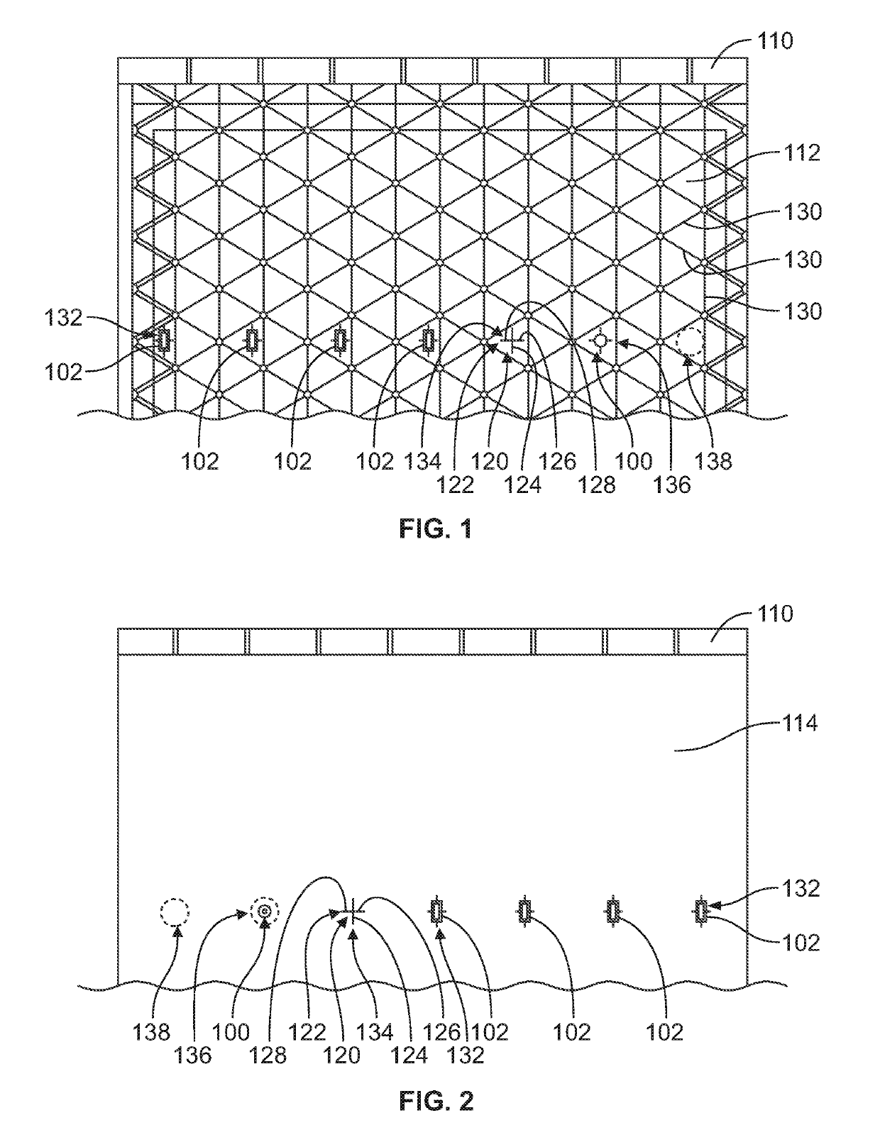
[0027]FIG. 1 illustrates a portion of the component locating apparatus 100 in accordance with an exemplary embodiment. FIG. 2 illustrates another portion of the component locating apparatus 100 in accordance with an exemplary embodiment. The component locating apparatus 100 is used for alignment of components 102 to be mounted on opposite sides of a structural wall 110. The structural wall 110 has a first side 112 and a second side 114 opposite the first side 112. FIG. 1 illustrates a portion of the component locating apparatus 100 located relative to the first side 112 of the structural wall 110 and FIG. 2 illustrates another portion of the component locating apparatus 100 located relative to the second side 114 of the structural wall 110.

[0028]The component locating apparatus 100 is used during manufacturing to provide markings on the structural wall 110 for precise alignment of the components 102. In an exemplary embodiment, the components 102 are sensors used for monitoring the ...


PUM

PropertyMeasurementUnit
magneticaaaaaaaaaa
attractive magnetic forceaaaaaaaaaa
magnetic forceaaaaaaaaaa

Abstract

A component locating apparatus for alignment of components on opposite sides of a structural wall includes a source magnet and a clone magnet. The source magnet has a magnetic centroid positioned relative to a locating feature and is successively held against the first side of the structural wall at a plurality of spaced apart source positions. The clone magnet has a marking opening at a magnetic centroid and is magnetically held against the second side of the structural wall by an attractive magnetic force at clone positions corresponding to the source positions. The magnetic centroids are aligned by the attractive magnetic force and the marking opening allows an operator to mark the second side of the structural wall at the magnetic centroid of the clone magnet at each of the clone positions to mirror, on the second side, the source positions corresponding to the component locating template.

Description

GOVERNMENT LICENSE RIGHTS[0001]This invention was made with government support under Contract NNM07AB03C, awarded be National Aeronautics and Space Administration (NASA). The government has certain rights in the invention.BACKGROUND[0002]The subject matter herein relates generally to a component locating apparatus and a method for alignment of components on opposite sides of a structural wall.[0003]In some systems, it may be desirable to accurately position components on opposite sides of a structural wall or panel. For example, sensors may need to be accurately positioned on opposite sides of a structural wall for sensing characteristics of the structural wall. For example, strain gages, temperature sensors, position sensors and the like may need to be positioned on opposite sides of the structural wall, such as to monitor the interior surface and the exterior surface of the structural wall at the same location on the structural wall. Locating the component on one side may be simpl...

Claims


Application Information

Patent Timeline
Patent Type & Authority Patents(United States)
IPC IPC(8): H05K13/04G01D5/12H01F7/02
CPCH01F7/021H05K13/04G01D5/12H01F7/0247
Inventor SWITZER, STEVE DUANEHANSEN, BRETT ALLEN
Owner THE BOEING CO
Features
  • R&D
  • Intellectual Property
  • Life Sciences
  • Materials
  • Tech Scout
  • Unparalleled Data Quality
  • Higher Quality Content
  • 60% Fewer Hallucinations
Learn More