Intake/outlet pipe optimization method for rotary engine

a technology of intake/outlet pipe and rotary engine, which is applied in the direction of machines/engines, mechanical equipment, instruments, etc., can solve the problems of insufficient air intake, inability to change without hardware modification, and confined power output of rotary engine, so as to enhance engine power output, improve air intake status of engine, and enhance power output performance

Active Publication Date: 2020-03-24
NAT CHUNG SHAN INST SCI & TECH
View PDF17 Cites 0 Cited by
  • Summary
  • Abstract
  • Description
  • Claims
  • Application Information

AI Technical Summary

Benefits of technology

[0008]In view of the shortcomings of the prior art, a primary objective of the present invention is to overcome the shortcomings by providing an intake / outlet pipe optimization method for a rotary engine. Wherein the pressure wave in the intake pipe together with the pressure in the air chamber of the rotary engine are adequately adjusted by the appearance alternation of the intake / outlet pipe to improve the air intake status of the engine and enhance the power output performance. Without changing the design of engine body, the shape, length, diameter, and angle of the intake / outlet pipe can be adjusted. Compared with the conventional straight intake / outlet pipe, the shape of the intake pipe of the invention is tapered to adjust the pressure of the air pipe and increase the air intake, to enhance the engine power output.
[0015]Through using the simulation software package, the determination of the optimal combination of the pipe length, the pipe diameter, the pipe shape, and pipe angle, and hence an optimized power output for the rotary engine can be more efficient, accurate, and time saving. Since a series of trials and errors for obtaining the optimized power output can be skipped and omitted, while the correct results can be obtained in a very short period of time.
[0018]Different combinations of the pipe length, pipe diameter, pipe shape, and pipe angle described in the step (B) can be used to adjust the amplitude and frequency of the pressure wave in the intake pipe in accordance with the instantaneous chamber pressure, the engine can be situated at a proper or better air intake status, and the mass of air intake will be increased to enhance the performance.
[0020]Wherein, the design of the intake pipe or the outlet pipe is the same as that of the intake / outlet pipe optimization method for a rotary engine, and the pressure wave motion in the pipe is adjusted by the pipe length, pipe diameter, pipe shape, and pipe angle to achieve a better air intake condition.
[0022]In the present invention, the rotary engine power output performance can be enhanced by a design that optimizes the pipe length, pipe diameter, pipe shape, and pipe angle of the intake / outlet pipe to provide an optimized combination of pipe length, pipe diameter, pipe shape, and pipe angle for various intake / outlet pipes of the rotary engine, in achieving an optimized power output for the rotary engine.

Problems solved by technology
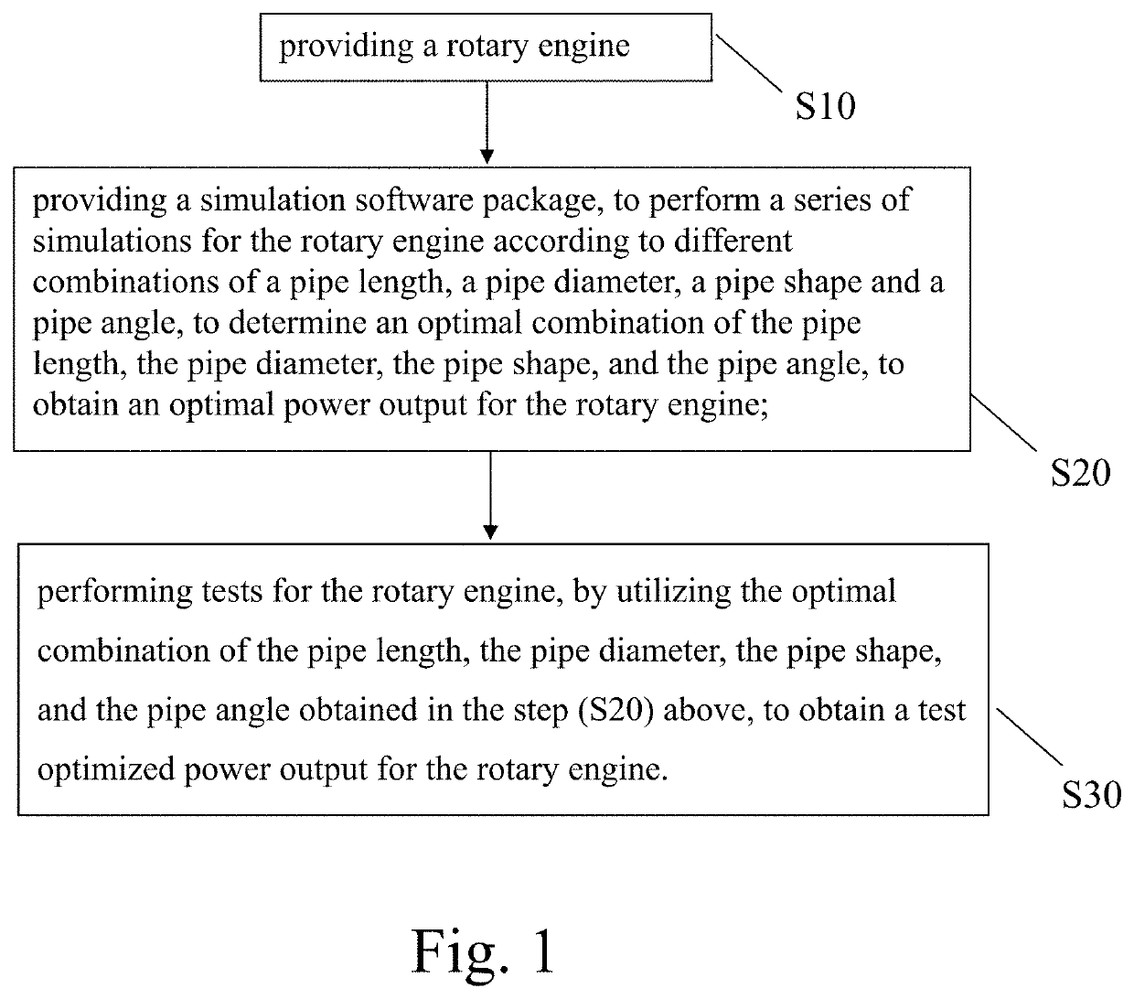
Unlike a general piston engine that can control the intake and exhaust timing by adjusting the intake / exhaust valves to achieve an optimized status, the power output of the rotary engine is confined to the arrangement of its fixed geometric appearances and cannot be changed without hardware modification.
On the other hand, if the pressure is higher in the air chamber than the intake pipe, the air in the chamber will flow reversely into the intake pipe, meaning that the air intake process temporarily stops, or even more the air flows out from the intake pipe, and thus resulting in an insufficient air intake.
Presently, most of the methods of enhancing the engine performance emphasizes on the appearance of the combustion chamber or the ignition timing, and thus incurring a higher cost and a longer time for modifying the engine body or using an additional turbocharger to provide a higher inlet pressure and a greater air intake to enhance the performance.
However, a too-high pressure in the intake pipe will increase the fuel consumption rate, and a portion of fuel gas is discharged from the outlet pipe, and thus failing to comply with the economic and environmental protection requirements.
(refer to Abstract, (0002), (0005)) However, in real life, the installation sites are quite often subjected to rather stringent space limitations, so that the change of the lengths of the intake and / or exhaust fluid paths is not sufficient to meet the installation requirements of an engine, and not able to enhance the power output of an engine as required.
Therefore, presently, the design and performance of the intake and outlet pipe for a rotary engine is not quite satisfactory, and it leaves much room for improvement.

Method used


Image

  • Intake/outlet pipe optimization method for rotary engine
  • Intake/outlet pipe optimization method for rotary engine
  • Intake/outlet pipe optimization method for rotary engine

Examples


embodiment 1

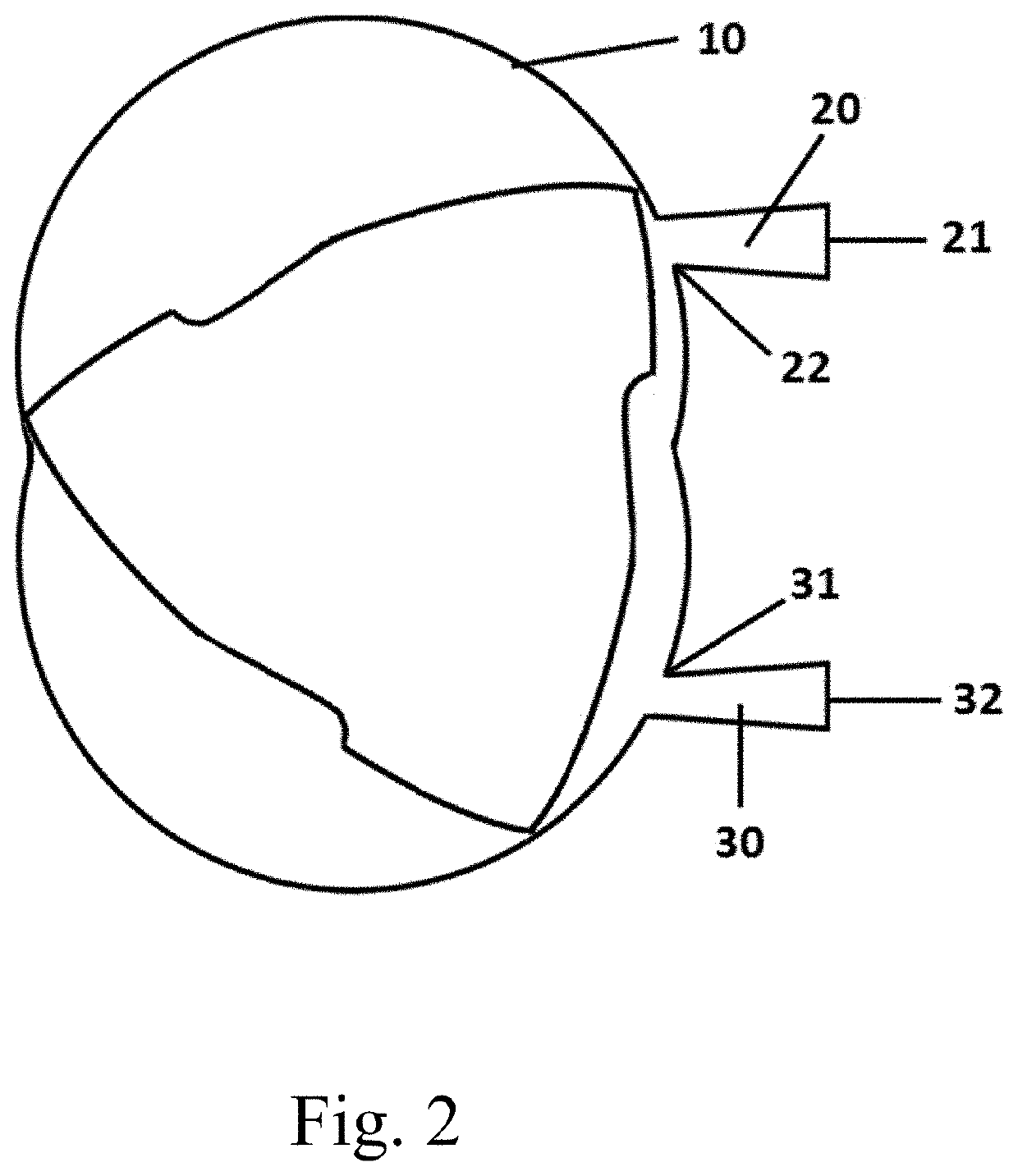
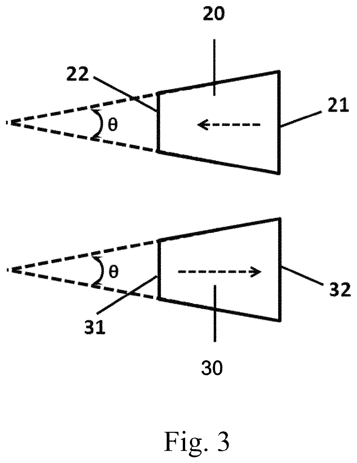
[0056]Refer to FIGS. 3 and 4 for a schematic diagram showing the shape and angle of an intake / outlet pipe of a rotary engine according to the present invention; and a perspective view of an intake / outlet pipe optimization rotary engine according to the present invention. As shown in FIGS. 3 and 4, a rotary engine body 10 is provided, and the engine supplies a power of 32 horsepower with original intake / outlet (approximately equal to 22.37 KW) at 6800 revolutions per minute (rpm). The outlet pipe 30 geometry is fixed in length, diameter and pipe shape. The tapered intake pipe 20 has a pipe diameter of 31.5 mm at the engine side, 8-degree pipe taper angle, a pipe length variation from 50 mm-1000 mm, and an engine performance test is conducted to obtain a test result showing that the length of the intake pipe can affect the engine performance and peak at around 700 mm in length about 16.8%.

embodiment 2

[0057]A rotary engine body 10 is provided, and the engine supplies a power of approximately 32 hp. Under a rotation speed of 6800 revolutions per minute (rpm), the pipe length, pipe diameter and pipe shape of the inversely tapered outlet pipe 30 are fixed, and the intake pipe 20 has a pipe length of 400 mm, a constant pipe taper angle of 2 degrees, and pipe diameter variation from 25 mm-40 mm at the engine side, and an engine performance test is conducted to obtain a test result showing that the diameter of the intake pipe can affect the engine performance and peak the output power by 16.9% at 35 mm in diameter.

[0058]Summing up the above, in the present invention, the rotary engine power output performance can be enhanced by a design that optimizes the pipe length, pipe diameter, pipe shape, and pipe angle of the intake / outlet pipe simultaneously, to provide an optimized combination of pipe length, pipe diameter, pipe shape, and pipe angle for various intake / outlet pipes of the rota...


PUM


Abstract

An intake / outlet pipe optimization method for a rotary engine, comprising the steps of: (A) providing a rotary engine; (B) providing a simulation software package, to perform a series of simulations for the rotary engine according to different combinations of a pipe length, a pipe diameter, a pipe shape and a pipe angle, to determine an optimal combination of the pipe length, the pipe diameter, the pipe shape, and pipe angle, to obtain an optimal power output for the rotary engine; and (C) performing tests for the rotary engine, by utilizing the optimal combination of the pipe length, the pipe diameter, the pipe shape, and pipe angle obtained in step (B), to obtain a test optimized power output for the rotary engine.

Description

CROSS-REFERENCE[0001]This application is a Continuation-In-Part (CIP) application of a pending application Ser. No. 15 / 077,903 filed on Mar. 22, 2016, entitled “INTAKE / OUTLET PIPE OPTIMIZATION METHOD FOR ROTARY ENGINE”.BACKGROUND OF THE INVENTIONField of Invention[0002]The present invention relates to an intake / outlet pipe optimization method for a rotary engine, and particularly to the method utilizing a software simulation package, to simulate, test, and obtain an optimized combination of the pipe length, pipe diameter, pipe shape, and pipe angle, to achieve an optimized power output for the rotary engine.The Prior Arts[0003]In general, a conventional rotary engine has the advantages of high power-to-weight ratio, small volume, fewer components, and compact structure, and the intake and outlet pipes of the engine are smooth pipes. The engine divides a cylinder into three air chambers by a triangular rotor. When the rotor rotates a round, the three air chambers can complete a cycle...

Claims


Application Information

Patent Timeline
Patent Type & Authority Patents(United States)
IPC IPC(8): G01M15/02F01C21/18F02B53/04F01C20/28F02B55/08F02B55/02F02B53/02F01C1/22
CPCF02B53/02F01C21/186F02B55/02F01C20/28F02B55/08G01M15/02F02B53/04F04C2240/806Y02T10/17F01C1/22Y02T10/12
Inventor JENG, DUN-ZENHSIEH, MING-CHUNLEE, CHIH-CHUANCHIEH, TING-HUA
Owner NAT CHUNG SHAN INST SCI & TECH
Why Eureka
Try Eureka