Adjustable foundation support system

a support system and adjustable technology, applied in the field of adjustable foundation support systems, can solve the problems of deficient foundation reinforcement systems, cracks, bowing, and even collapse of foundation walls, and achieve the effects of safe reinforcement of subterranean walls, reducing the number of parts used, and improving security

Active Publication Date: 2020-04-14
POWER BRACE
View PDF14 Cites 2 Cited by
  • Summary
  • Abstract
  • Description
  • Claims
  • Application Information

AI Technical Summary

Benefits of technology

[0005]Therefore, it is a primary object, feature, or advantage of the invention to improve on or overcome the deficiencies in the art.
[0006]It is another object, feature, or advantage of the invention to provide an extension system including extension support members configured to allow a vertical support member to be extended as needed on site without the need for welding or carrying a variety of support member lengths.
[0007]It is still yet a further object, feature, or advantage of the invention to provide extension brackets to operatively secure a first, vertical support member to a second, vertical, and typically shorter support member.
[0008]It is still yet a further object, feature, or advantage of the invention to place the means for fastening the vertical support members around a portion of the vertical support member and a portion of the extension bracket and to preferably hold the vertical support member in close proximity with the extension bracket.
[0009]It is still yet a further object, feature, or advantage of the invention to provide additional extension support members that are secured to one another through one or more nut and bolt assemblies to improve securement between the vertical support members and the extension brackets and to strengthen the extension support member by resting the extension support member on the bottom nut and bolt assembly while simultaneously providing a sheath or additional bracketing to further support by the top nut and bolt assembly.
[0010]It is still yet a further object, feature, or advantage of the invention to reduce the number of parts used to form the extension system, while still safely reinforcing a subterranean wall.

Problems solved by technology

As a result, upon exposure to excessive lateral forces, foundation walls often crack, bow, push inward, or even collapse.
The foundation reinforcement systems commonly known in the art are deficient for a variety reasons.

Method used


Image

  • Adjustable foundation support system
  • Adjustable foundation support system
  • Adjustable foundation support system

Examples


Embodiment Construction

[0035]The following definitions and introductory matters are provided to facilitate an understanding of the present invention.

[0036]The singular terms “a,”“an,” and “the” include plural referents unless context clearly indicates otherwise. Similarly, the word “or” is intended to include “and” unless the context clearly indicate otherwise. The word “or” means any one member of a particular list and also includes any combination of members of that list.

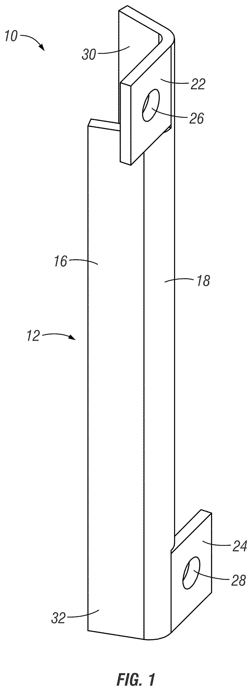
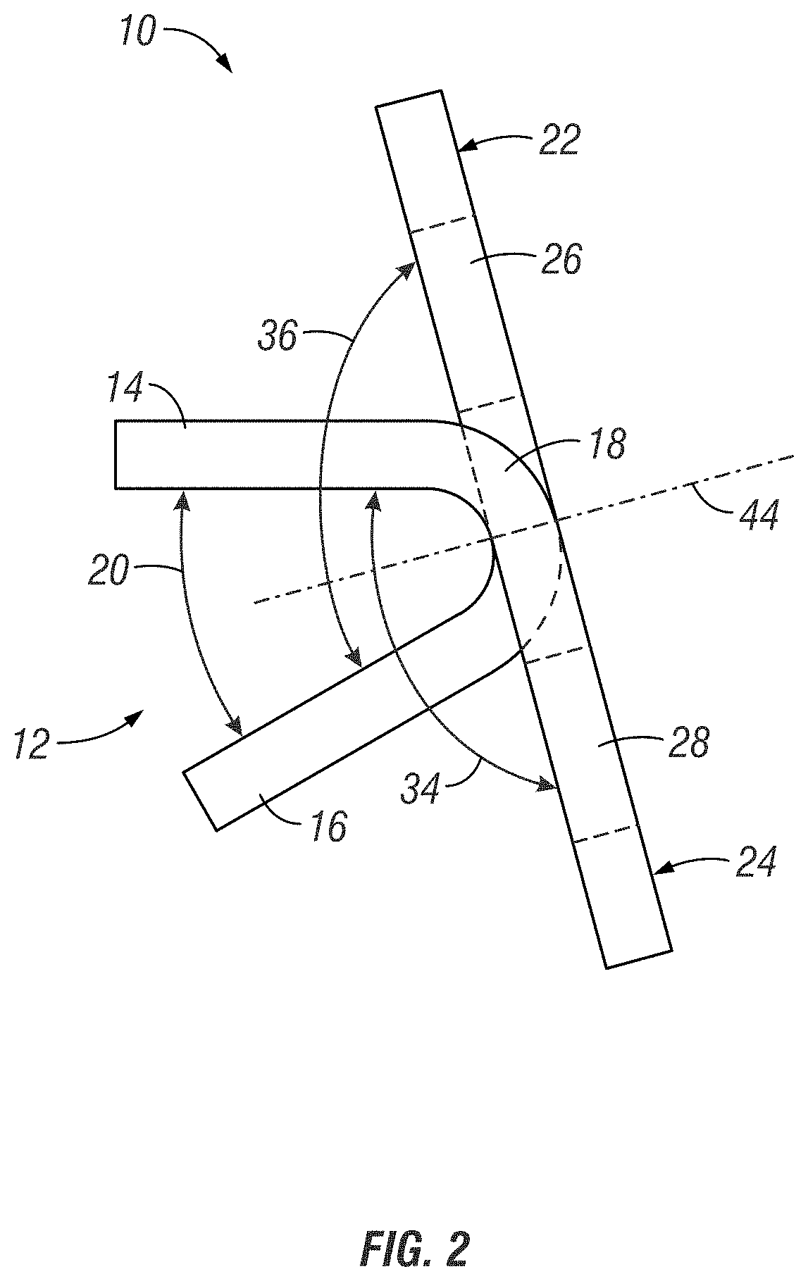
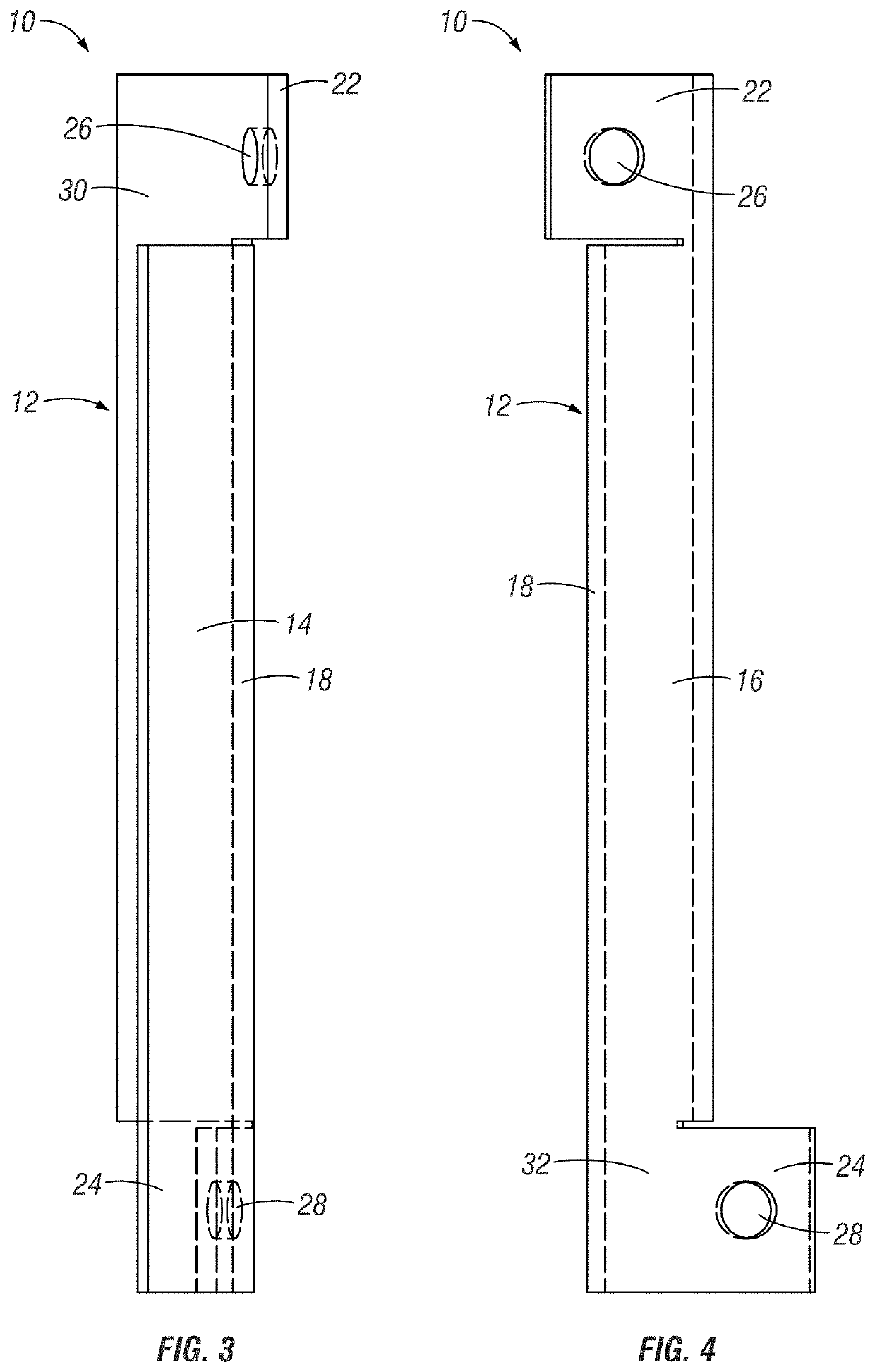
[0037]Reference is made to the accompanying drawings which form a part hereof, and in which is shown by way of illustration specific embodiments in which the invention may be practiced. These embodiments of the invention will be described in detail with reference to the drawings, wherein like reference numerals represent like parts throughout the several views. These embodiments are described in sufficient detail to enable those skilled in the art to practice the invention, and it is to be understood that other embodiments may be utiliz...


PUM

PropertyMeasurementUnit
convex angleaaaaaaaaaa
obtuse angleaaaaaaaaaa

Abstract

An extension support member includes a bracket or web having a first planar portion or leg, a second planar portion or leg, an acute, concave angle between the first planar portion or leg and the second planar portion or leg, and a bend or backbone joining the first planar portion or leg to the second planar portion or leg. The extension support member also includes is a first mounting portion or tab joined to the second planar portion or leg via the bend or backbone at a first, convex obtuse angle and a second mounting portion or tab joined to the first planar portion or leg via the bend or backbone at a second obtuse, convex angle. The first mounting portion and the second mounting portion are located at opposite ends of the bracket or web.

Description

CROSS-REFERENCE TO RELATED APPLICATIONS[0001]The Present Applications is a Continuation-in-part Patent Applications of co-pending U.S. Utility patent application Ser. No. 15 / 939,404, filed Mar. 29, 2018, which is a Conversion Patent Applications of U.S. Provisional Patent Application Ser. No. 62 / 515,824, filed Jun. 6, 2017. These applications are herein incorporated by reference in their entirety, including without limitation, the specification, claims, and abstract, as well as any figures, tables, or drawings thereof.FIELD OF THE INVENTION[0002]The present disclosure relates generally to an adjustable foundation support system. More particularly, but not exclusively, the present disclosure relates to a system utilizing special extension support members that allow two vertical support members to be secured to one another.BACKGROUND OF THE INVENTION[0003]Many of today's homes include basements, which are at least partially subterranean. The basement foundation walls are designed to s...

Claims


Application Information

Patent Timeline
Patent Type & Authority Patents(United States)
IPC IPC(8): E04B1/58E04B1/41E02D27/02E04G23/02B21D5/02E04B1/24E04B1/38E04B1/00
CPCE02D27/02B21D5/02E04B1/58E04G23/0229E04B1/40E04B1/0007E04B2001/246E04B2001/405E04B1/5812E04B2001/5875B21D35/001E04B2001/389E04B1/388
Inventor HEADY, TIMOTHY P.HEADY, CHARLES W.
Owner POWER BRACE
Why Eureka
Try Eureka