
Rotor for rotary electric machine

a rotary electric machine and rotor core technology, which is applied in the direction of dynamo-electric machines, magnetic circuit rotating parts, magnetic circuit shape/form/construction, etc., can solve the problems of prolonged life of metal molds, achieve the effect of preventing magnetic loss, reducing the weight of the outer circumferential side relative to the magnet inserting hole of the rotor core, and reducing the ripple of the rotary electric machin

Active Publication Date: 2020-06-09
HONDA MOTOR CO LTD
View PDF20 Cites 0 Cited by
  • Summary
  • Abstract
  • Description
  • Claims
  • Application Information

AI Technical Summary

Benefits of technology

[0019]According to the rotor of (1), since the hole portion is provided at the outer circumferential side relative to the magnet inserting hole of the rotor core approximately on the d-axis of each of the magnetic poles formed by the permanent magnets, torque ripples of the rotary electric machine can be reduced. Also, since the hole portion is provided, a change in magnetic flux in a gap between the outer circumferential surface of the rotor core and the stator can be prevented. Thus, magnetic loss is prevented. Further, since the hole portion is provided, weight of the outer circumferential side relative to the magnet inserting hole of the rotor core is reduced. Thus, a centrifugal force occurring during rotation is reduced, so that the rotor can be rotated at a higher speed.
[0020]According to the rotor of (2), since the hole portion is the long hole having the major axis directed in the radial direction of the rotor core, torque in a region of a low advance angle is not reduced, and the torque ripple can be reduced in a region in which an advance angle is advanced.
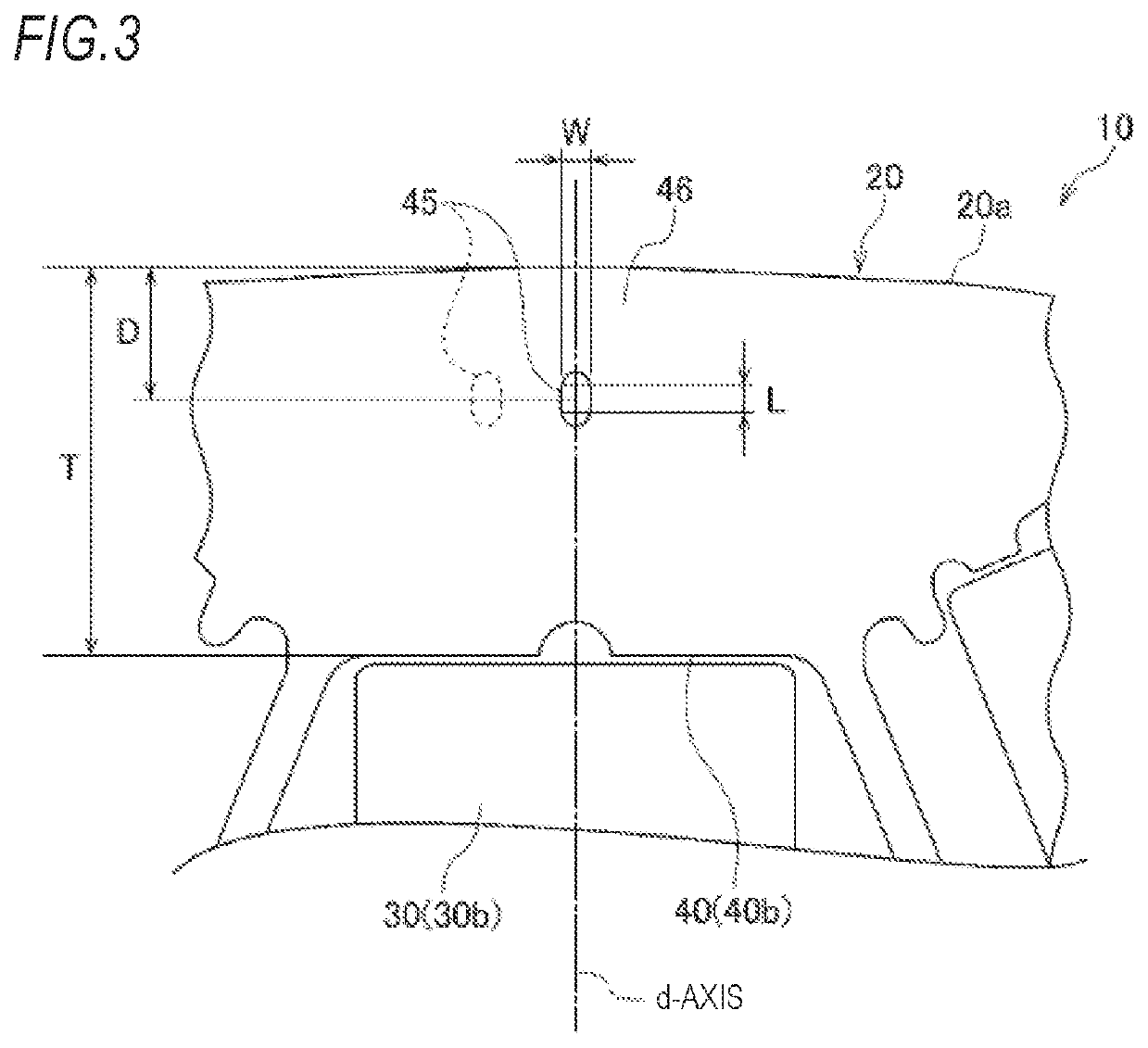
[0021]According to the rotor of (3), since the width of the hole portion in the direction of the minor axis is equal to or greater than twice of the thickness of one steel sheet forming the rotor core formed of stacked steel sheets, wear of a metal mold can be reduced when the steel sheets are formed by punching using the metal mold. As a result, a life of the metal mold is prolonged.
[0022]According to the rotor of (4), since the depth from the outer circumferential surface of the rotor core to the center of the hole portion in the direction of the major axis is less than the half of the thickness of the rotor yoke in the direction of the d-axis, an effect of reducing the torque ripple due to the hole portion is larger.

Problems solved by technology

As a result, a life of the metal mold is prolonged.

Method used


Image

  • Rotor for rotary electric machine
  • Rotor for rotary electric machine
  • Rotor for rotary electric machine

Examples


first embodiment

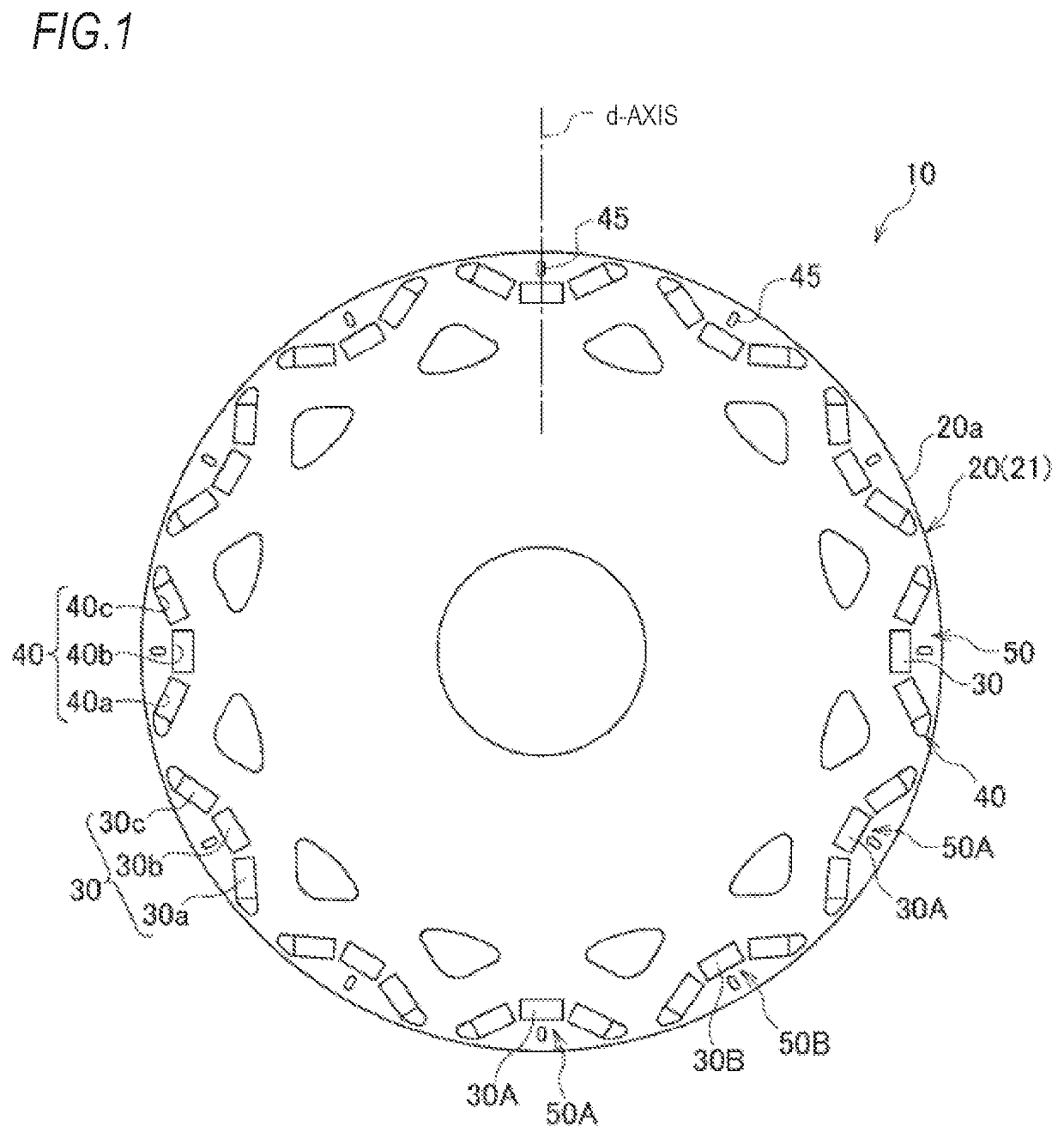
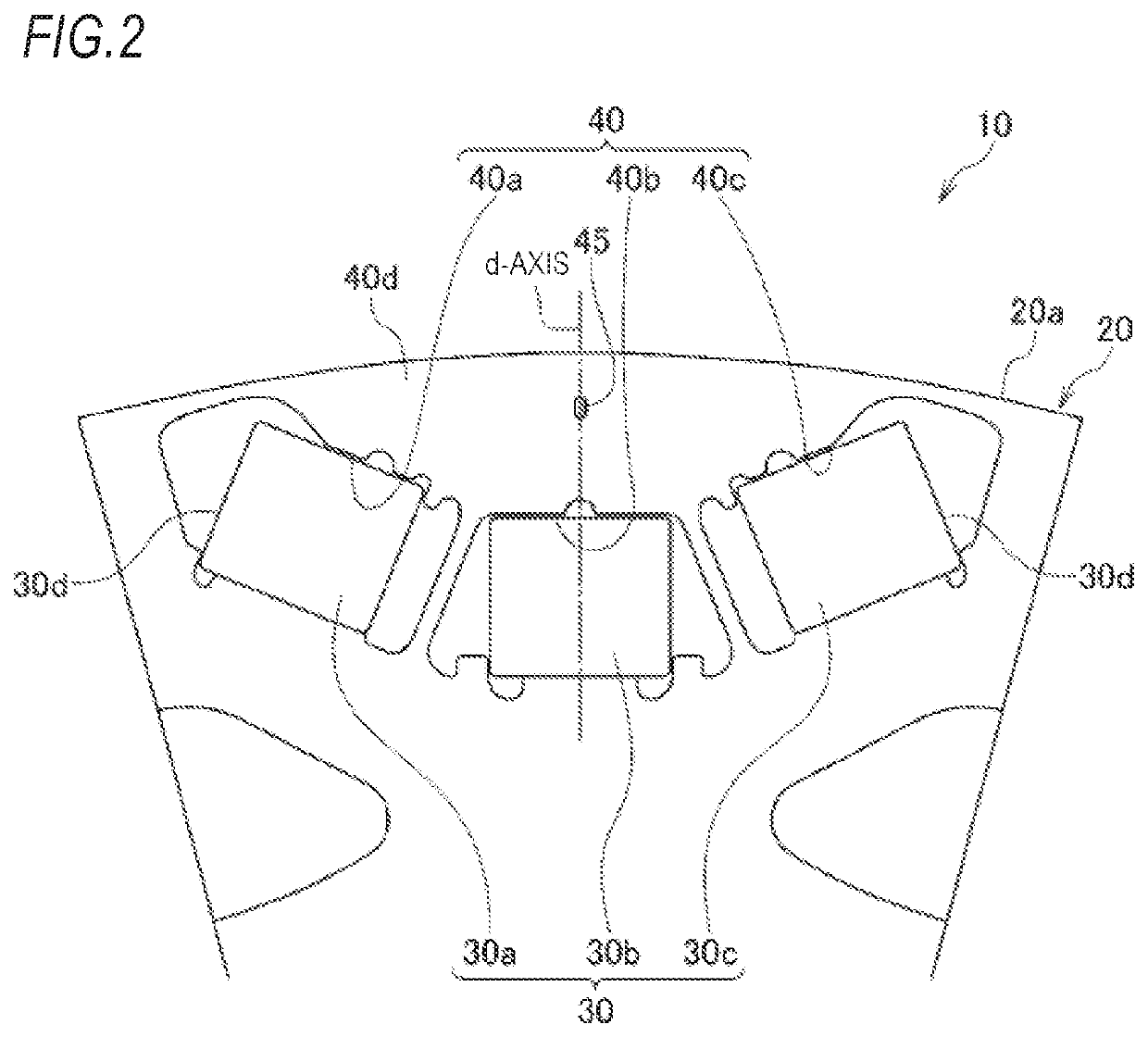
[0034]FIG. 1 is a front view of a rotor for a rotary electric machine according to a first embodiment. FIG. 2 is an enlarged view illustrating one magnetic pole part in the rotor for the rotary electric machine illustrated in FIG. 1. FIG. 3 is an enlarged front view of a main part of the rotor for the rotary electric machine illustrated in FIG. 2.

[0035]In the rotary electric machine, a rotor 10 having a plurality of permanent magnets 30 is rotatably provided at an inner circumferential side of a stator (not shown) having an annular shape. The rotor 10 is configured to rotate by applying a current to coils wound around the stator.

[0036]As illustrated in FIGS. 1 to 3, the rotor 10 of the rotary electric machine of the present embodiment includes a rotor core 20 formed with a plurality of magnet inserting holes 40 in a circumferential direction thereof, and the permanent magnets 30 which are inserted into and fixed in the magnet inserting holes 40.

[0037]The rotor core 20 is formed by s...

second embodiment

[0054]FIG. 9 is an enlarged front view of a main part of a rotor for a rotary electric machine according to a second embodiment. A rotor 10A for the rotary electric machine of the second embodiment is different from the rotor 10 for the rotary electric machine of the first embodiment in that one magnetic pole part 50 is formed by two permanent magnet pieces 30a and 30c disposed in a magnet inserting hole 40 formed in an approximate V shape. A configuration other than this point is the same as in the first embodiment, and components common with those of FIG. 1 are given the same reference signs in FIG. 9.

[0055]In the rotor 10A for the rotary electric machine of the second embodiment, similarly to the rotor 10 for the rotary electric machine of the first embodiment, an effect of reducing torque ripple due to a hole portion 45 can be obtained.

third embodiment

[0056]FIG. 10 is an enlarged front view of a main part of a rotor for a rotary electric machine according to a third embodiment. A rotor 10B for a rotary electric machine of the third embodiment is different from the rotor 10 for the rotary electric machine of the first embodiment in that one magnetic pole part 50 is formed by one permanent magnet 30 disposed in a magnet inserting hole 40 formed in a linear shape in a direction perpendicular to a radial direction of the rotor 10B of the rotary electric machine. A configuration other than this point is the same as in the first embodiment, and components common with those of FIG. 1 are given the same reference signs in FIG. 10.

[0057]In the rotor 10B for the rotary electric machine of the third embodiment, since reluctance torque is low, an effect of reducing torque ripple due to a hole portion 45 is low. However, the effect can be obtained compared to a case where no hole portion 45 is formed.

[0058]The present invention is not limited...


PUM


Abstract

There is provided a rotor for a rotary electric machine including a rotor core of an approximately annular shape having a plurality of magnet inserting holes formed at predetermined intervals in a circumferential direction thereof, and a plurality of permanent magnets inserted into the magnet inserting holes. A rotor yoke on at least an outer circumferential side relative to the magnet inserting holes of the rotor core is formed of a magnetic material. The outer circumferential side relative to the magnet inserting holes of the rotor core has a hole portion approximately on a d-axis of each magnetic poles formed by the permanent magnets.

Description

CROSS-REFERENCE TO RELATED APPLICATION[0001]This application claims priority from Japanese Patent Application No. 2017-031531 filed on Feb. 22, 2017, the entire contents of which are incorporated herein by reference.TECHNICAL FIELD[0002]The present invention relates to a rotor for a rotary electric machine.BACKGROUND ART[0003]As a rotor used in a rotary electric machine, there has been known a rotor in which a plurality of permanent magnets are arranged in a rotor core at predetermined intervals in a circumferential direction (for example, see JP-B-5278003, JP-A-2002-78260 and WO2012 / 014836).[0004]A rotor for an electric motor described in JP-B-5278003 reduces torque ripples and iron loss by arranging a position of a groove, which is provided in an outer circumferential portion of the rotor, at an electric angle of 40° to 44° with respect to a center line of a magnetic pole closest to the groove. Alternatively, the electric angle is set to 44° to 53° to reduce harmonic components in...

Claims


Application Information

Patent Timeline
Patent Type & Authority Patents(United States)
IPC IPC(8): H02K1/27H02K29/03
CPCH02K1/2766H02K1/276H02K2213/03H02K29/03H02K2201/03
Inventor AZUSAWA, KEISUKE
Owner HONDA MOTOR CO LTD
Learn More