Rotor for rotary electric machine
a rotary electric machine and rotor core technology, which is applied in the direction of dynamo-electric machines, magnetic circuit rotating parts, magnetic circuit shape/form/construction, etc., can solve the problems of prolonged life of metal molds, achieve the effect of preventing magnetic loss, reducing the weight of the outer circumferential side relative to the magnet inserting hole of the rotor core, and reducing the ripple of the rotary electric machin
- Summary
- Abstract
- Description
- Claims
- Application Information
AI Technical Summary
Benefits of technology
Problems solved by technology
Method used
Image
Examples
first embodiment
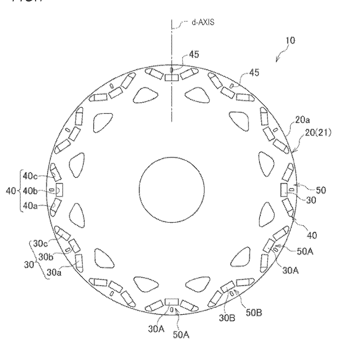
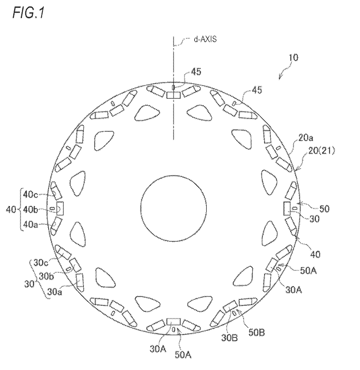
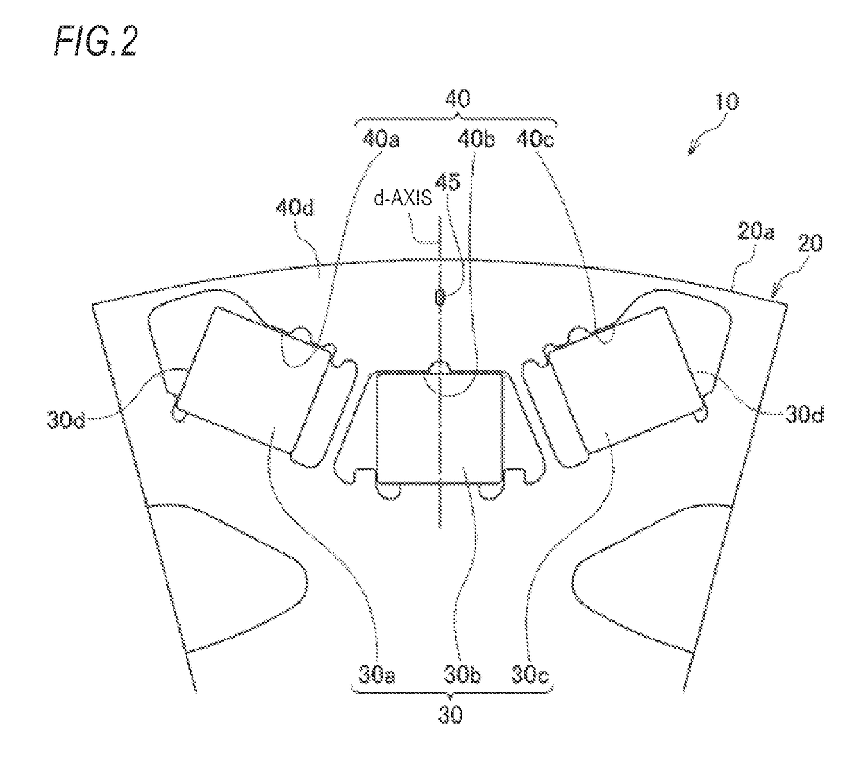
[0034]FIG. 1 is a front view of a rotor for a rotary electric machine according to a first embodiment. FIG. 2 is an enlarged view illustrating one magnetic pole part in the rotor for the rotary electric machine illustrated in FIG. 1. FIG. 3 is an enlarged front view of a main part of the rotor for the rotary electric machine illustrated in FIG. 2.
[0035]In the rotary electric machine, a rotor 10 having a plurality of permanent magnets 30 is rotatably provided at an inner circumferential side of a stator (not shown) having an annular shape. The rotor 10 is configured to rotate by applying a current to coils wound around the stator.
[0036]As illustrated in FIGS. 1 to 3, the rotor 10 of the rotary electric machine of the present embodiment includes a rotor core 20 formed with a plurality of magnet inserting holes 40 in a circumferential direction thereof, and the permanent magnets 30 which are inserted into and fixed in the magnet inserting holes 40.
[0037]The rotor core 20 is formed by s...
second embodiment
[0054]FIG. 9 is an enlarged front view of a main part of a rotor for a rotary electric machine according to a second embodiment. A rotor 10A for the rotary electric machine of the second embodiment is different from the rotor 10 for the rotary electric machine of the first embodiment in that one magnetic pole part 50 is formed by two permanent magnet pieces 30a and 30c disposed in a magnet inserting hole 40 formed in an approximate V shape. A configuration other than this point is the same as in the first embodiment, and components common with those of FIG. 1 are given the same reference signs in FIG. 9.
[0055]In the rotor 10A for the rotary electric machine of the second embodiment, similarly to the rotor 10 for the rotary electric machine of the first embodiment, an effect of reducing torque ripple due to a hole portion 45 can be obtained.
third embodiment
[0056]FIG. 10 is an enlarged front view of a main part of a rotor for a rotary electric machine according to a third embodiment. A rotor 10B for a rotary electric machine of the third embodiment is different from the rotor 10 for the rotary electric machine of the first embodiment in that one magnetic pole part 50 is formed by one permanent magnet 30 disposed in a magnet inserting hole 40 formed in a linear shape in a direction perpendicular to a radial direction of the rotor 10B of the rotary electric machine. A configuration other than this point is the same as in the first embodiment, and components common with those of FIG. 1 are given the same reference signs in FIG. 10.
[0057]In the rotor 10B for the rotary electric machine of the third embodiment, since reluctance torque is low, an effect of reducing torque ripple due to a hole portion 45 is low. However, the effect can be obtained compared to a case where no hole portion 45 is formed.
[0058]The present invention is not limited...
PUM
 Abstract
Description
Claims
Application Information
 - R&D
- Intellectual Property
- Life Sciences
- Materials
- Tech Scout
- Unparalleled Data Quality
- Higher Quality Content
- 60% Fewer Hallucinations
Browse by: Latest US Patents, China's latest patents, Technical Efficacy Thesaurus, Application Domain, Technology Topic, Popular Technical Reports.
© 2025 PatSnap. All rights reserved.Legal|Privacy policy|Modern Slavery Act Transparency Statement|Sitemap|About US| Contact US: help@patsnap.com


