Check patentability & draft patents in minutes with Patsnap Eureka AI!

Expandable stent and methods of crimping and expanding such stent

a stent and expansion technology, applied in the field of expandable stents and methods of crimping and expanding such stents, can solve the problems of critical sizing, oversizing and undersizing of stents designed with nitinol, and the inability to readily adjust the diameter of stents

Active Publication Date: 2020-10-06
STRAIT ACCESS TECH HLDG
View PDF8 Cites 0 Cited by
  • Summary
  • Abstract
  • Description
  • Claims
  • Application Information

AI Technical Summary

Benefits of technology

[0049]the stiffened portions of the first member of the first arm on the one hand and the second member of the first arm on the other hand are disposed on opposite sides of a virtual plane that: (i) extends between the respective first junctions; and (ii) is transverse the longitudinal axis of the stent,such that, upon radial expansion of the stent from a radially crimped condition under the influence of an external force, tension in the lattice members at the first junctions causes rotation of the stiffened portions of the first member of the first arm at the first junctions, thereby causing the ends of the stiffened portions distal the second member of the first arm to rotate towards each other.

Problems solved by technology

The diameter of stents designed with nitinol cannot be readily adjusted, which makes sizing critical.
There are risks of both oversizing and undersizing, which could lead to valve leakage and / or migration.
In the case of trans-catheter valves, continuous contact force between the stent and the heart may lead to compression of the electrical conduction structures in the heart, which in turn may necessitate the implantation of a permanent pacemaker.
These sheaths require more complex delivery systems to allow operators to control the unsheathing operation.
A drawback of this stent is that the barbs protrude even when the stent is in a radially compressed state.GB2513195 “A stent for a prosthetic heart valve” describes an expandable stent with arms, which arms are caused to protrude radially by tethers that form part of the valve deployment device.
A drawback of this device is that deployment of the arms is complex, requiring a custom dilatation device.U.S. Pat. No. 8,992,608 “Everting heart valve” describes an expandable stent including arms that are caused to protrude radially upon axial compression of the stent.
A drawback of this device is that deployment of the arms requires axial compression of the stent and a custom dilatation device.U.S. Pat. No. 8,216,301 “Implant implantation unit” describes an expandable stent and arms that protrude from the outer radial wall of the stent and resiliently pivot radially outwards from the stent.
A drawback of this device is that the arms must be restrained from pivoting radially outwards during insertion of the device into a patient.WO2011 / 002996 “Apparatus and method for replacing a diseased cardiac valve” describes an expandable stent wherein radial expansion of the stent causes opposed arms to protrude radially to capture a structure on a vessel wall between the opposed arms.
A drawback of this device is that the degree to which the arms protrude radially from the stent wall must accurately be determined to ensure proper engagement of the arms and the formation on the vessel.
Should the arms not protrude sufficiently radially properly to engage the structure on the vessel wall, slippage of the stent along the vessel may cause the structure on the vessel to pass beyond the arm, unable again properly to become engaged by the stent.

Method used


Image

  • Expandable stent and methods of crimping and expanding such stent
  • Expandable stent and methods of crimping and expanding such stent
  • Expandable stent and methods of crimping and expanding such stent

Examples


Embodiment Construction

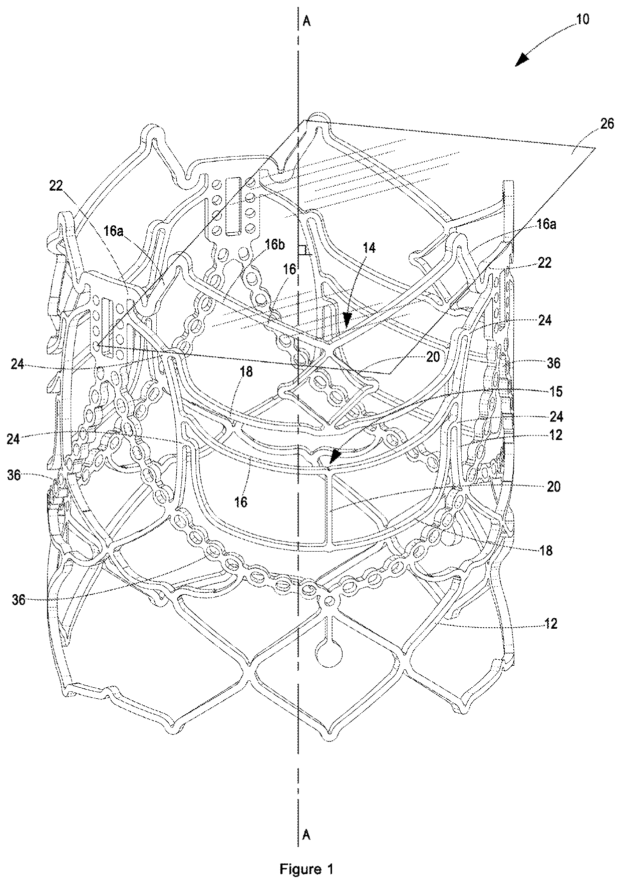
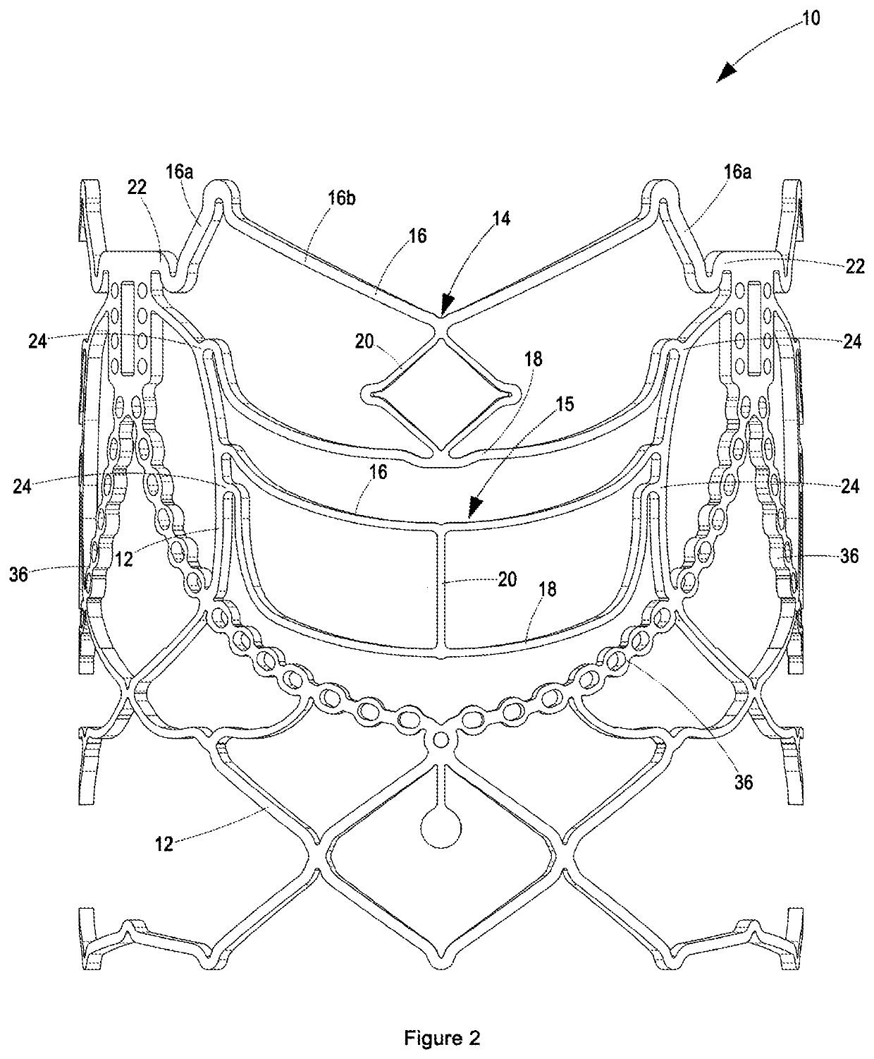
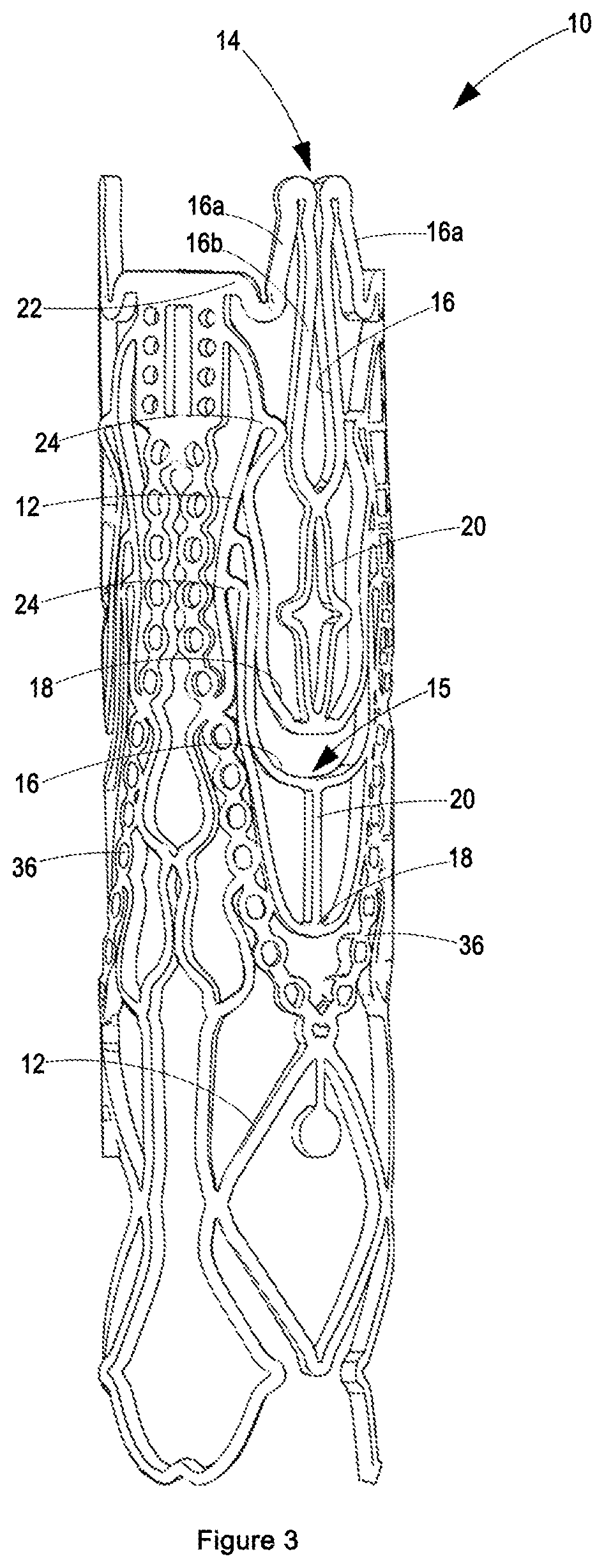
[0072]With reference to FIGS. 1 to 6 of the drawings, an expandable cylindrical stent 10 is formed by laser cutting a single right circular cylindrical tube to form lattice members 12, first arms 14 and second arms 15. The lattice members 12 and arms 14 and 15 form an integral part of the cylindrical wall of the stent 10, which is typically between 18 mm and 30 mm in outer diameter.

[0073]The lattice members 12 form a lattice, in the sense that they are connected to each other at junctions, which formation permits the stent 10 to be crimped (i.e. radially compressed) under the influence of an enveloping external radially compressive force. The lattice members 12 need not necessarily form a regular diamond-shaped structure. For a 23 mm outer diameter stent 10 (which is typically made from a 23 mm outer diameter tube), the lattice member width may vary between 100 μm and 1000 μm, but is most preferably between 200 μm and 600 μm.

[0074]The stent 10 may be made of stainless steel, cobalt-...


PUM


Abstract

An expandable stent comprises a cylindrical wall made up of lattice members connected to each other, at least one first arm and at least one second arm. The first arm comprises: a first non-linear member that is connected at each of its axial ends to a lattice member at respective first junctions; a second non-linear member connected at each axial end to a lattice member; and at least one bridge member extending between the first member and the second member. The second arm comprises: a first non-linear member that is connected at each of its axial ends to a lattice member; a second non-linear member connected at each axial end to a lattice member; and at least one bridge member extending between the first member and the second member. The second member of the first arm is generally U-shaped, extending from its axial ends towards: (i) a first axial end of the stent; and (ii) towards the bridge of the first arm. The second member of the second arm is generally U-shaped, extending from its axial ends towards: (i) a first axial end of the stent; and (ii) towards the bridge of the second arm. The first arm is disposed at a second axial end of the stent, and the second arm is: (i) axially spaced from the first arm towards the first axial end of the stent; and (ii) axially aligned with the first arm. Furthermore, the first member and the second member of each of the first and second arms are connected to lattice members at their axial ends only. Upon radial expansion of the stent from a radially crimped condition under the influence of an external force, tension in: (i) the bridge of the first arm; and (ii) the bridge member of the second arm, causes the second members of both the first and second arms to protrude radially outwards, respectively.

Description

BACKGROUND[0001]The present invention relates to an expandable stent and methods of crimping and expanding such stent. More particularly, the present invention relates to an expandable cylindrical stent with axially spaced arms that extend axially in the same direction, which stent can plastically be deformed to a crimped condition, and which crimped stent can be expanded radially with the aid of a dilatation device to cause the axially spaced arms to protrude radially beyond the radial wall of the stent.[0002]In the recent years, there has been a big movement towards minimally invasive surgeries, which has led to substantial development in the field of vascular devices, particularly vascular stents and trans-catheter heart valves. This is mainly as a result of the reduced surgical time, risks and recovery time as well as hospitalisation time of the patients involved with minimally invasive treatments.[0003]The main aims of vascular stents and trans-catheter heart valves are to rein...

Claims


Application Information

Patent Timeline
Patent Type & Authority Patents(United States)
IPC IPC(8): A61F2/24A61F2/86
CPCA61F2/2418A61F2/2415A61F2220/0008A61F2/86A61F2/2427A61F2220/0025
Inventor NELSON, GRANT LEIGHPARK, KENNETH STUARTVAN BREDA, BRADEN SYDNEY CLIVEBEZUIDENHOUT, DEONZILLA, PETERAPPA, HARISH
Owner STRAIT ACCESS TECH HLDG
Features
  • R&D
  • Intellectual Property
  • Life Sciences
  • Materials
  • Tech Scout
  • Unparalleled Data Quality
  • Higher Quality Content
  • 60% Fewer Hallucinations
Learn More