
Force-closure or form-closure positioning of surgical templates for guided implant dentistry

a template and implant dentistry technology, applied in the field of force-closure or form-closure positioning of surgical templates for guided implant dentistry, can solve the problems of inconvenient and easy-to-repeat inconvenient and easy-to-use surgical procedures, and inconvenient placement of surgical templates, etc., to achieve unique, accurate and repeatable placement

Active Publication Date: 2020-10-20
DENTSPLY IMPLANTS NV
View PDF18 Cites 1 Cited by
  • Summary
  • Abstract
  • Description
  • Claims
  • Application Information

AI Technical Summary

Benefits of technology

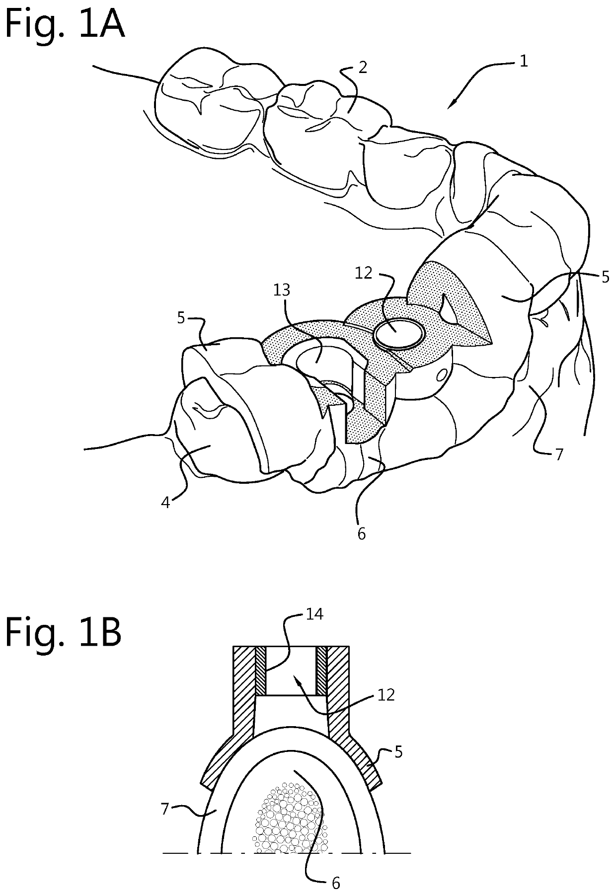
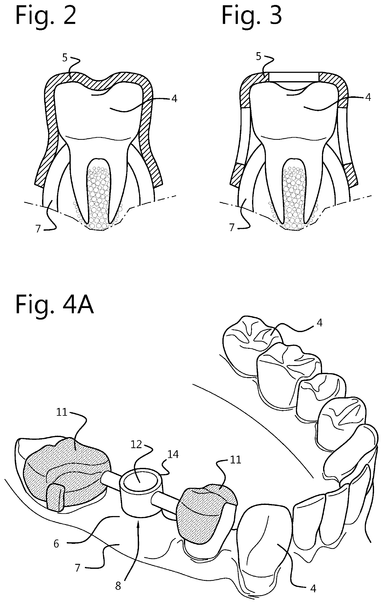
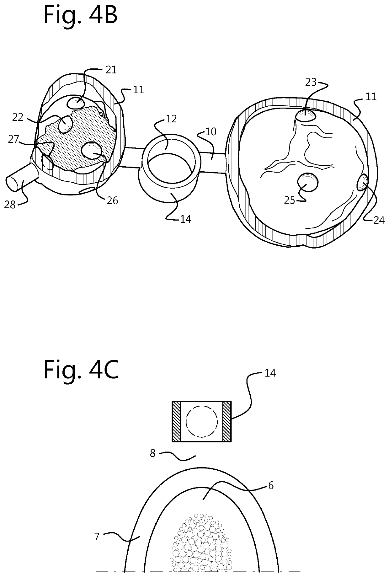
The present invention provides a surgical template that can be attached to a 3D supporting surface using point to area contacts, called minimally 7 (seven) contact features. These contact features can be spherical, cylindrical, pyramidal, or conic contact points. By using a screw clamping mechanism, the template and the surface can be brought into force-closure when the screw is tightened. This allows for accurate and repeatable placement of the template. The limited number of contact features and the force-closure make this technology unique and effective.

Problems solved by technology

Deviations, with respect to the original supporting surface, in areas of the surgical template that support on the supporting surface, will result in incorrect positioning of the surgical template onto the supporting surface.
Manually holding the surgical template in place adds complexity to the surgical operation as it requires additional assistance, i.e. an ‘extra hand’, which also can result in more limited operational freedom and more limited intra-oral visibility.
However, the shape of these contact features described in that patent is not specifically defined and can be, although limited in contact area, continuous in nature.
Contact over a continuous area is susceptible to interfering deformations, or protrusions that can result from imperfect scanning or manufacture.
However, the surgical template contacts the supporting surface in a continuous manner and therefore does not comply with a pre-determined location condition except not surpassing the boundary of the supporting surface.
Since the position of the template is not determined prior to manufacturing, also the position of a guidance feature for surgical instruments is not determined prior to surgery, which makes this a cumbersome procedure to allow guidance of surgical instruments according to a pre-operative plan.
The device is also very large in size which takes up a lot of the headroom especially above the molars.

Method used


Image

  • Force-closure or form-closure positioning of surgical templates for guided implant dentistry
  • Force-closure or form-closure positioning of surgical templates for guided implant dentistry
  • Force-closure or form-closure positioning of surgical templates for guided implant dentistry

Examples


Embodiment Construction

[0084]The present invention is described with respect to particular embodiments and with reference to certain drawings but the invention is not limited thereto but only by the claims. The drawings described are only schematic and are non-limiting. Where the term comprising is used in the description and claims, it does not exclude other elements or steps. Furthermore, the terms first, second, third and the like in the description and in the claims, are used for distinguishing between similar elements and not necessarily for describing a sequential or chronological order. It is to be understood that the terms so used are interchangeable under appropriate circumstances and that the embodiments of the invention described herein are capable of operation in other sequences than described or illustrated herein.

[0085]In an aspect of embodiments of the present invention a surgical template is provided which can be used in assisting in a surgical procedure such as placement of dental implant...


PUM


Abstract

Surgical templates and methods of manufacture to assist in a surgical procedure such as dental implant placement, where the positioning of the surgical template onto its supporting surface is achieved through using a limited number of contact features that are located such that a force-closure or form closure positioning of the surgical template with respect to the supporting surface is achieved.

Description

[0001]The present invention relates to surgical templates, to a method of manufacturing these and a method of designing these, whereby the surgical templates have a repeatable form-closure or force-closure positioning. The present invention also relates to software which can assist in designing surgical templates such as for dental implants as well as images of the surgical templates produced having a repeatable form-closure or force-closure positioning.BACKGROUND OF THE INVENTION[0002]A dental surgical template is a custom-made device intended for use in surgery for example in assisting placement of dental implants. More specifically, a surgical template can be intended to help the intended user prepare an osteotomy for dental implants and to help the intended user place dental implants according to a pre-operative plan. The surgical template is preferably prepared in a patient specific manner, i.e. it has dimensions that are specific to the anatomy of each patient.[0003]Convention...

Claims


Application Information

Patent Timeline
Patent Type & Authority Patents(United States)
IPC IPC(8): A61C1/08A61C8/00A61C9/00
CPCA61C1/082A61C9/0053A61C8/0089A61C1/084A61B34/10A61C8/009A61B2034/105A61B2034/108A61B2017/00526
Inventor MASSOELS, JOPOLSPOEL, WOUTERMUYLAERT, DOMINIK
Owner DENTSPLY IMPLANTS NV
Learn More