
Slide rail assembly and slide rail kit thereof

a technology of slide rail and slide rail kit, which is applied in the direction of supporting structure mounting, furniture parts, mechanical equipment, etc., can solve the problem of inability to work on the inner rail

Active Publication Date: 2021-11-02
KING SLIDE WORKS CO LTD +1
View PDF17 Cites 3 Cited by
  • Summary
  • Abstract
  • Description
  • Claims
  • Application Information

AI Technical Summary

Benefits of technology

This patent describes a mechanism for synchronizing the movement of three rails. The first rail has a blocking portion that prevents the second rail from moving when it is extended. The second rail has a pre-determined retracted position and when it reaches that position, the blocking portion prevents it from moving further. The third rail moves in response to the movement of the second and first rails, and a contact feature pushes against a synchronization device to deform it and allow the contact feature to cross it. This mechanism ensures precise synchronization of the rails.

Problems solved by technology

This may result in the projection of the inner rail being unable to work collaboratively with the two resilient fingers, followed by the middle rail failing to be pulled out in the opening direction together with the inner rail.

Method used


Image

  • Slide rail assembly and slide rail kit thereof
  • Slide rail assembly and slide rail kit thereof
  • Slide rail assembly and slide rail kit thereof

Examples


Embodiment Construction

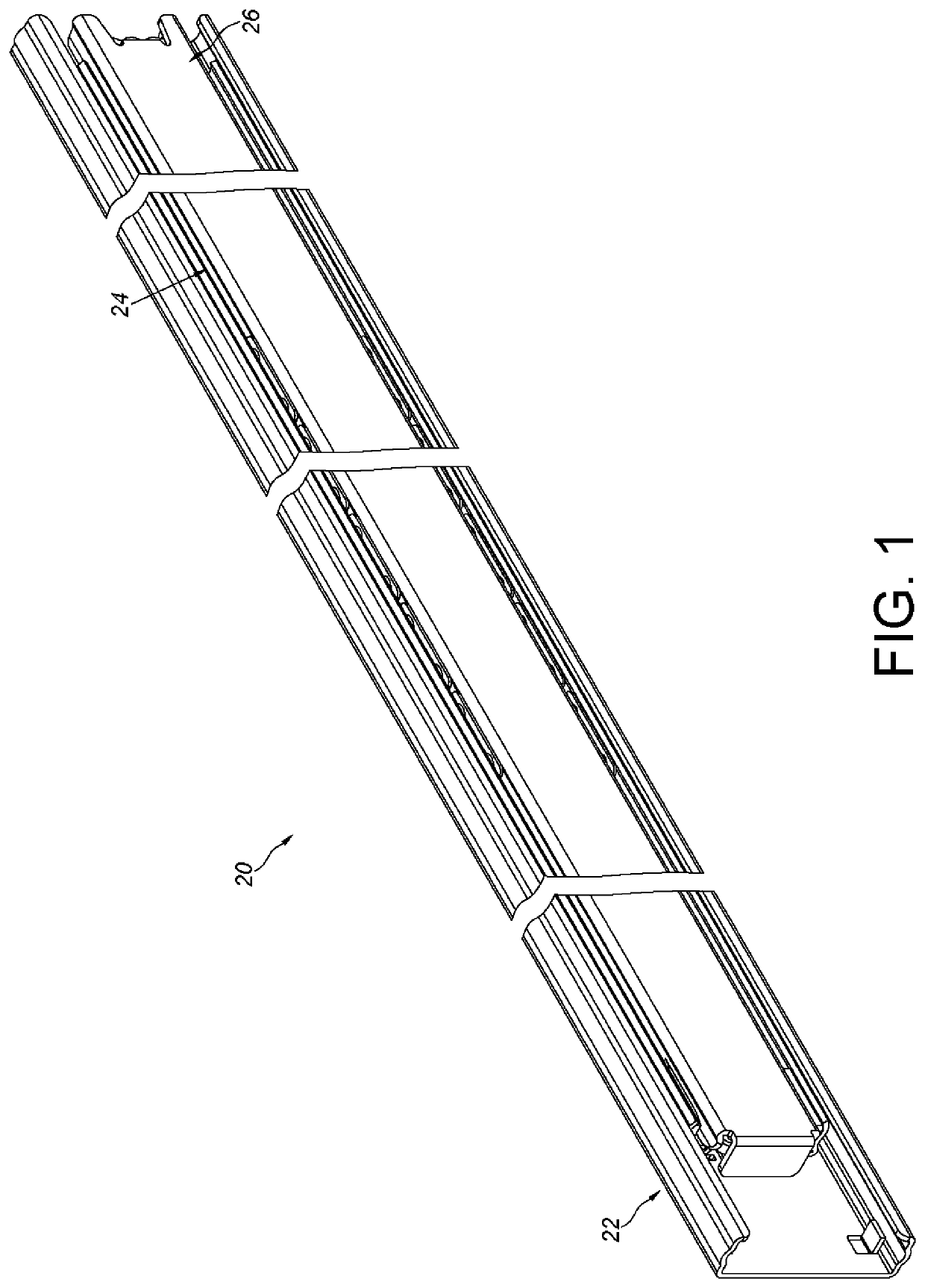
[0028]As shown in FIG. 1, a slide rail assembly 20 according to an embodiment of the present invention comprises a plurality of slide rails, and a first rail 22, a second rail 24 and a third rail 26 are illustrative of examples herein. The second rail 24 is moveably disposed between the first rail 22 and the third rail 26.

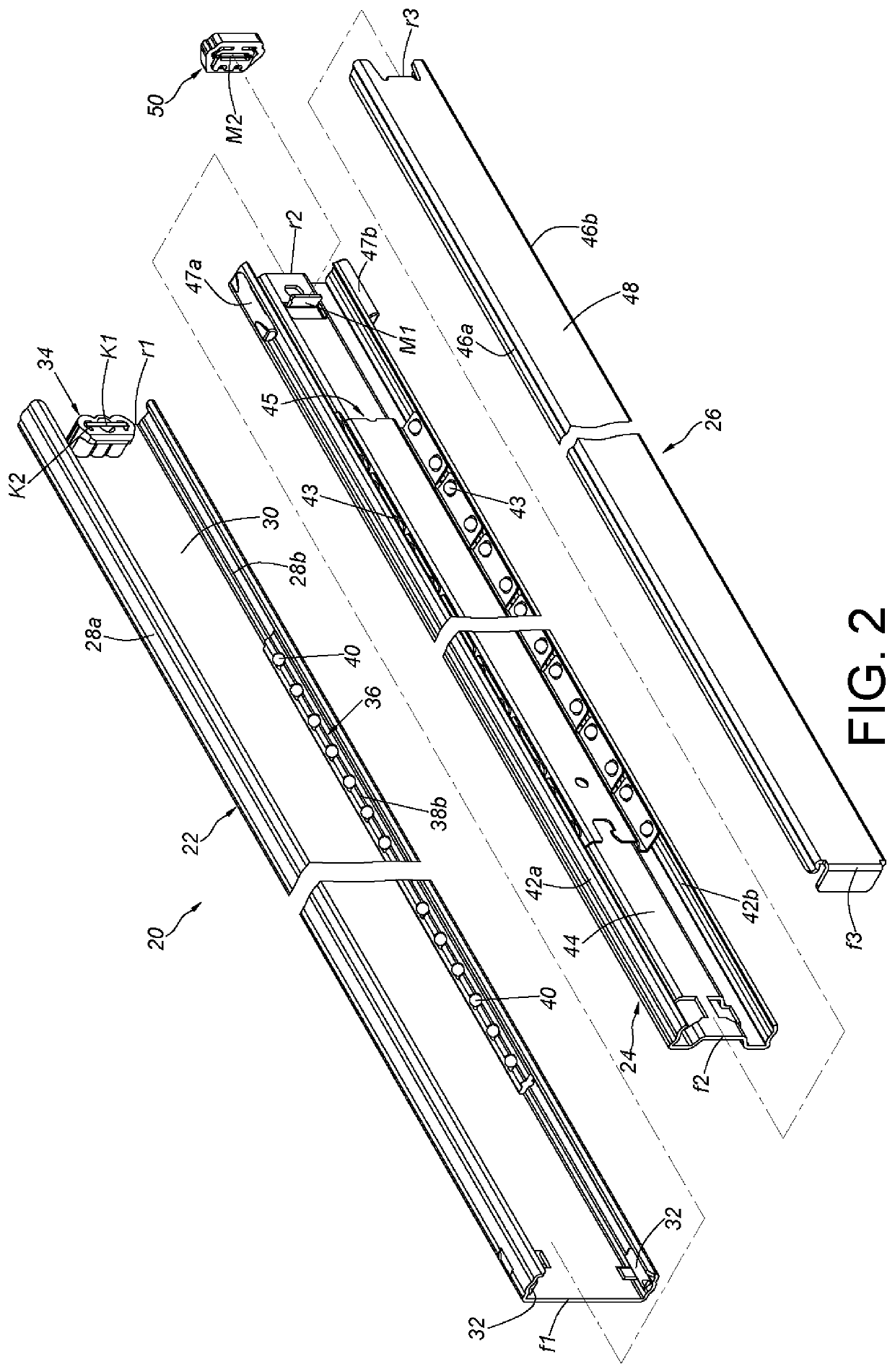
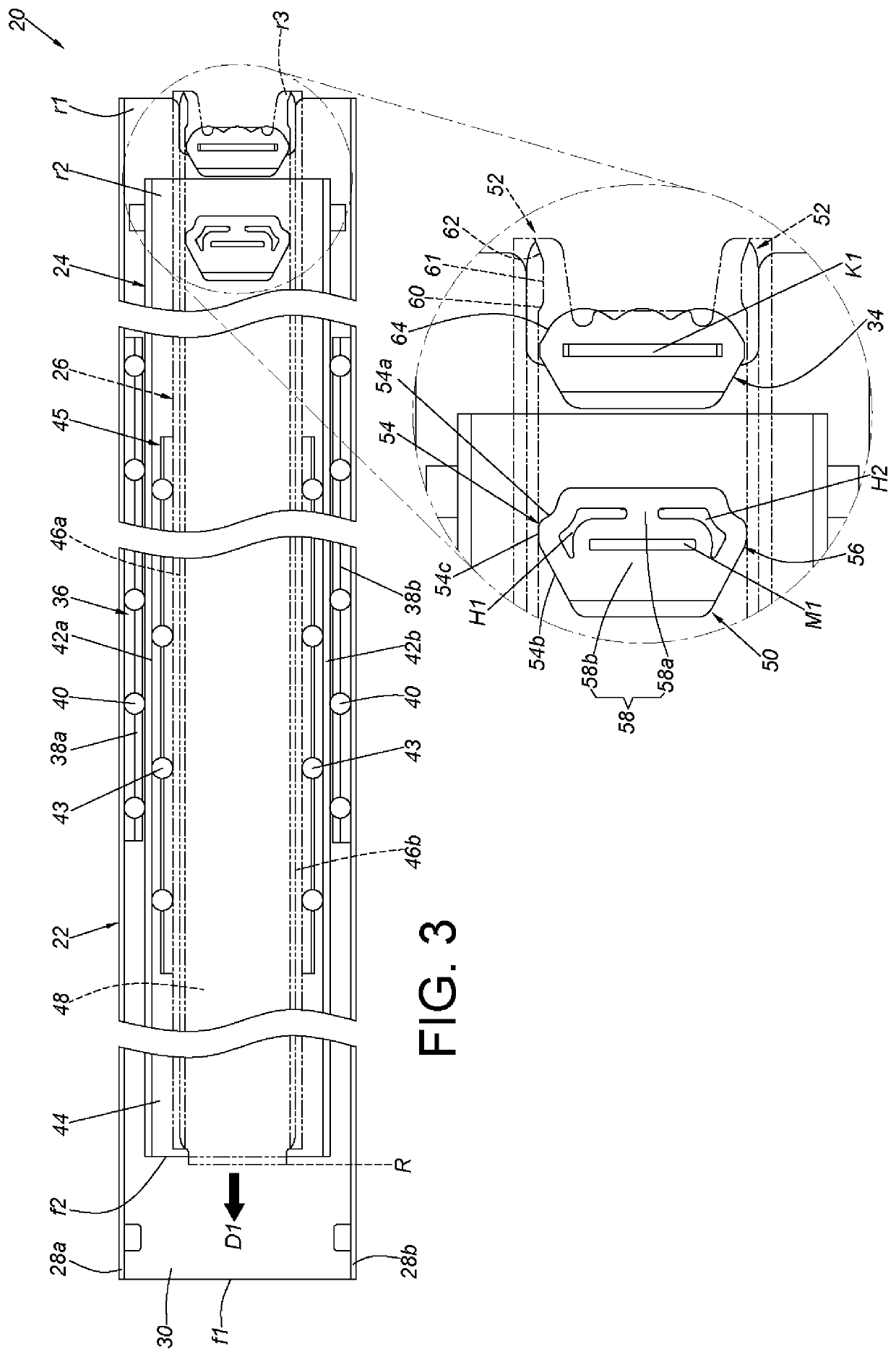
[0029]As shown in FIGS. 2 and 3, the first rail 22 comprises a first wall 28a, a second wall 28b and a longitudinal wall 30 connected between the first wall 28a and the second wall 28b of the first rail 22. The first wall 28a, the second wall 28b and the longitudinal wall 30 of the first rail 22 collectively define a first passage containing the second rail 24. The first rail 22 comprises a first end portion f1 and a second end portion r1, such as a front end portion and a rear end portion, but the present invention is not limited thereto. Preferably, the first end portion f1 adjacent to the first rail 22 is arranged with at least one first blocking portion 32; one...


PUM


Abstract

A slide rail assembly includes a first rail, a second rail, a third rail, a synchronization device and a contact feature. The second rail is displaceable relative to the first rail. The third rail is displaceable relative to the second rail. The synchronization device is arranged on one of the second rail and the third rail. The contact feature is arranged on the other of the second rail and the third rail. The third rail and the second rail can synchronously displace relative to the first rail through the collaboration between the synchronization device and the contact feature.

Description

BACKGROUND OF THE INVENTION1. Field of the Invention[0001]The present invention relates to a slide rail assembly, and more particularly, to a slide rail assembly capable of synchronously displacing two slide rails.2. Description of the Prior Art[0002]Prior art U.S. Pat. No. 5,181,782A discloses a telescopic slide rail assembly comprising an outer rail, a middle / intermediate rail and an inner rail / drawer section. The middle rail is arranged with a stop block, and the inner rail has a projection. As shown in FIGS. 3-5 of the prior art, when the inner rail is pulled in an opening direction, the inner rail can contact the resilient fingers of the stop block via its projection, so that the middle rail can be pulled out in the opening direction together with the inner rail.[0003]As shown in FIG. 1 or FIG. 7 of the prior art, the ends of the resilient fingers are not connected to each other; that is, the two resilient fingers are designed to be open-ended with a gap therebetween. Therefore...

Claims


Application Information

Patent Timeline
Patent Type & Authority Patents(United States)
IPC IPC(8): A47B88/45A47B88/473A47B88/493A47B88/46F16C29/02
CPCA47B88/45A47B88/46A47B88/473A47B88/493F16C29/02A47B2210/007A47B88/443H05K7/1489A47B2210/0081
Inventor CHEN, KEN-CHINGHUANG, SHIH-LUNGJHAO, YI-SYUANWANG, CHUN-CHIANG
Owner KING SLIDE WORKS CO LTD
Learn More