Compact integrated GNSS antenna system with vertical semitransparent screen for reducing multipath reception

a gnss antenna and semi-transparent screen technology, applied in the field of compact antenna systems, can solve the problems of inability to operate high-precision gnss receivers normally, the height of the antenna also has to be limited, and the signal reflection from the ground is a considerable source of errors in gnss systems

Active Publication Date: 2022-05-10
TOPCON POSITIONING SYST INC
View PDF5 Cites 0 Cited by
  • Summary
  • Abstract
  • Description
  • Claims
  • Application Information

AI Technical Summary

Benefits of technology

[0009]In one embodiment, an antenna system includes a patch antenna installed onto a conducting housing of an integrated receiver and a vertical semitransparent screen intended for providing a required directivity pattern (DP) in the bottom hemisphere. The vertical semitransparent screen includes slots with a set of elements with such pre-set impedance that their availability does not cause antenna mismatch, and current in the vertical semitransparent screen provides additional electromagnetic field which is subtracted from the antenna field in the nadir direction.
[0010]Such a design enables implementing a low DP level in the bottom hemisphere, ensuring low overall antenna dimensions in plan view and vertical dimension.

Problems solved by technology

Signals reflected from the ground are a considerable source of errors in GNSS systems.
Then, if the lateral dimension of the ground plane is equal to the lateral dimension of the patch, DP level in the bottom hemisphere becomes the same as that of the upper hemisphere, which is unacceptable for normal operation of high-precision GNSS receivers.
When such an antenna is used with a housing of an integrated receiver, the antenna also has to be limited in height.

Method used


Image

  • Compact integrated GNSS antenna system with vertical semitransparent screen for reducing multipath reception
  • Compact integrated GNSS antenna system with vertical semitransparent screen for reducing multipath reception
  • Compact integrated GNSS antenna system with vertical semitransparent screen for reducing multipath reception

Examples


Embodiment Construction

[0029]Reference will now be made in detail to the preferred embodiments of the present invention, examples of which are illustrated in the accompanying drawings.

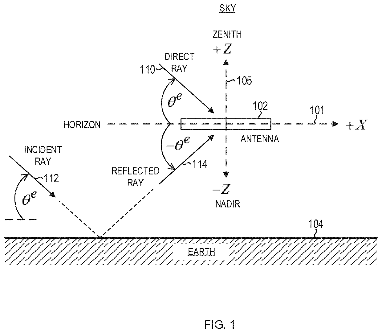
[0030]FIG. 1 shows a schematic of a global navigation satellite system (GNSS) antenna 102 positioned above the Earth 104. Herein, the term Earth includes both land and water environments. To avoid confusion with “electrical” ground (as used in reference to a ground plane), “geographical” ground (as used in reference to land) is not used herein. To simplify the drawing, supporting structures for the antenna are not show. Shown is a reference Cartesian coordinate system with X-axis 101 and Z-axis 105. The Y-axis (not shown) points into the plane of the figure. In an open-air environment, the +Z (up) direction, referred to as the zenith, points towards the sky, and the −Z (down) direction, referred to as the nadir, points towards the Earth. The X-Y plane lies along the local horizon plane.

[0031]In FIG. 1, electromagnetic waves ...


PUM


Abstract

An antenna system includes a right-hand circularly polarized antenna for receiving Global Navigation Satellite System (GNSS) signals and located on a receiver housing; a vertical semitransparent screen for providing an Down / Up ratioDU9⁢0=DU⁡(θe=9⁢0∘)=F⁡(-9⁢0∘)F⁡(9⁢0∘)of −13 dB or better for at least some GNSS frequencies; the semitransparent screen being connected to a ground plane of the antenna; the ground plane being connected to a conductive receiver housing; the semitransparent screen further comprising a horizontal slot to which sets of lumped impedance elements are connected. Each set includes several lumped elements; where the lumped elements are capacitors and / or inductors and / or resistors; where the lumped elements in each set are connected in parallel or series; and the semitransparent screen including at least 4 segments arranged symmetrically around the center of the antenna and connected to each other.

Description

BACKGROUND OF THE INVENTIONField of the Invention[0001]The present invention relates generally to antennas, and more particularly to a compact antenna system with a reduced antenna directivity pattern (DP) in the bottom hemisphere.Background of the Related Art[0002]Global navigation satellite systems (GNSSs) can determine locations with high accuracy. Such Global navigation satellite systems are widely used for high-precision positioning, such as the US Global Positioning System (GPS) and Russian global navigation system GLONASS, as well as European global navigation system (Galileo), Chinese navigation system BeiDou and some others. GNSSs are used in a wide range of applications, such as surveying, geology, and mapping. In a GNSS, a navigation receiver receives and processes radio signals transmitted by satellites located within a line-of-sight of the navigation receiver. A critical component of a GNSS is the receiver antenna. Key properties of the antenna are bandwidth, multipath ...

Claims


Application Information

Patent Timeline
Patent Type & Authority Patents(United States)
IPC IPC(8): G01S19/36G01S19/32H01Q5/30H01Q1/24H01Q1/48H01Q5/307H01Q9/04
CPCG01S19/36G01S19/32H01Q1/24H01Q1/48H01Q5/307H01Q9/0428H01Q9/0435H01Q9/0414H01Q5/40
Inventor TATARNIKOV, DMITRY VITALIEVICHGENERALOV, ALEXEY ANATOLIEVICHASTAKHOV, ANDREY VITALIEVICH
Owner TOPCON POSITIONING SYST INC
Why Eureka
Try Eureka