
Process cartridge, mounting mechanism for process cartridge and electrophotographic image forming apparatus

a technology of process cartridges and mounting mechanisms, applied in the field of processes, can solve the problems of excessive long movement distance, inability to insert the process cartridge b, and inability to move at the same tim

Inactive Publication Date: 2002-08-15
CANON KK
View PDF0 Cites 74 Cited by
  • Summary
  • Abstract
  • Description
  • Claims
  • Application Information

AI Technical Summary

Problems solved by technology

In such a case, the distance by which the moving guide 41 and process cartridge B slide relative to each other as the process cartridge B is subjected to the conveyance load, will be excessively long.
Therefore, it has become impossible for the process cartridge B to be inserted, unless the process cartridge B is inserted at an angle steeper than the normal angle.
Thus, neither does the opening / closing cover 15 open, nor is the image forming apparatus adversely affected.
Therefore, a relatively large amount of force is necessary for the disengagement.

Method used


Image

  • Process cartridge, mounting mechanism for process cartridge and electrophotographic image forming apparatus
  • Process cartridge, mounting mechanism for process cartridge and electrophotographic image forming apparatus
  • Process cartridge, mounting mechanism for process cartridge and electrophotographic image forming apparatus

Examples


Embodiment Construction

)

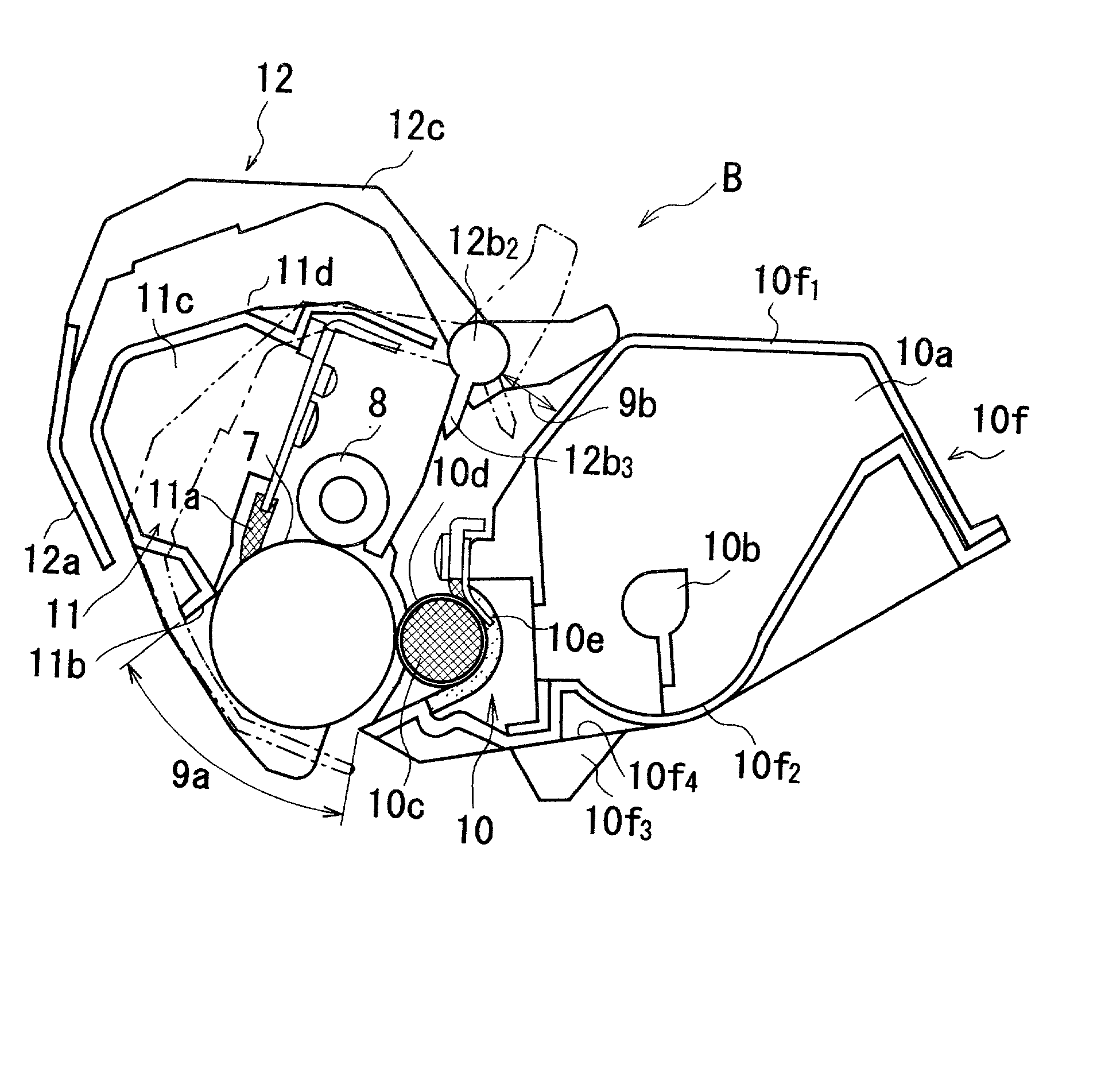
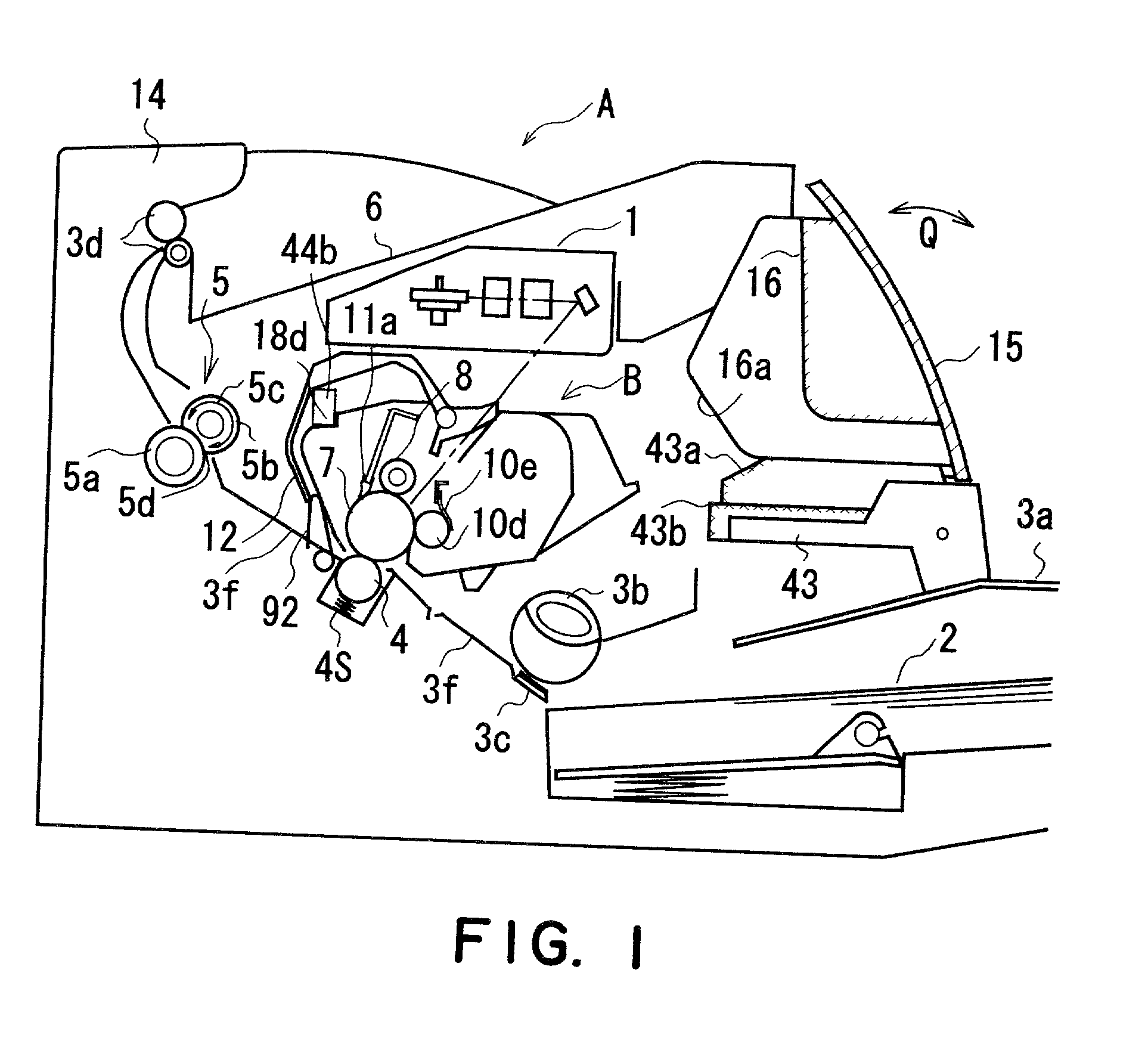
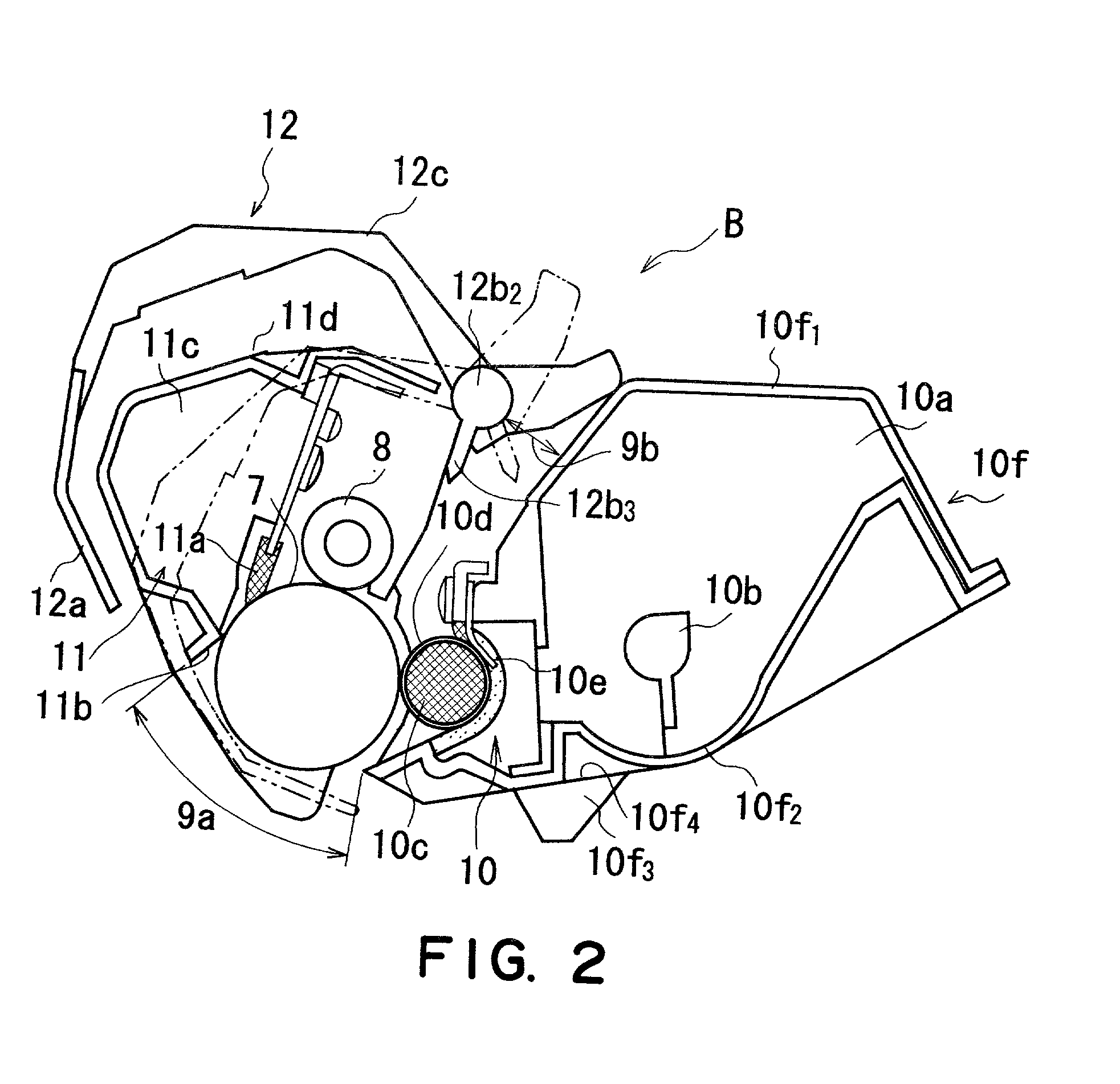
[0485] Hereinafter, the other embodiments of the present invention will be described in detail with reference to the appended drawings.

[0486] In the following description of the present invention, the lengthwise direction of the process cartridge B means the direction perpendicular (virtually perpendicular) to the direction in which the process cartridge B is mounted into or dismounted from the apparatus main assembly. It is parallel to the surface of the recording medium, and perpendicular to (virtually perpendicular) to the direction in which the recording medium is conveyed. The left and right of the process cartridge B coincides with the left and right of the recording medium as seen from above, and behind in terms of the direction in which the recording medium is conveyed. The top and bottom surfaces of the process cartridge B mean the surfaces of the process cartridge B which are at the top and bottom, facing upward, when the process cartridge B is in the apparatus main assem...


PUM


Abstract

A process cartridge detachably mountable to a main assembly of an electrophotographic image forming apparatus which includes an openable closing member, a first main assembly guide movable in interrelation with opening and closing action of the closing member, and a second main assembly guide, the process cartridge include a photosensitive drum; a first cartridge frame portion extending in a cartridge mounting direction to the main assembly, at one axial end portion of the drum; a first cartridge guide projected from the first cartridge frame portion, the first cartridge guide moving the cartridge toward a cartridge mounting position by movement of the first main assembly guide with the cartridge being supported on first main assembly guide, upon mounting of the cartridge to the main assembly; a second cartridge frame portion extended in the mounting direction at the other axial end portion of the drum; a second cartridge guide projected from the second cartridge frame portion, the second cartridge guide moving the cartridge toward a cartridge mounting position by movement of the second main assembly guide with the cartridge being supported on the second main assembly guide, when the cartridge is mounted to the main assembly of the apparatus; a first cartridge positioning portion for engaging with a first main assembly positioning portion provided in the main assembly to position the cartridge relative to the main assembly, the first cartridge positioning portion being projected outwardly from the first cartridge frame portion and coaxially with the drum at the one axial end of the drum; and a second cartridge positioning portion for engaging with a second main assembly positioning portion to position the cartridge relative to the main assembly when the cartridge is mounted to the main assembly, the second cartridge positioning portion being projected outwardly from the second cartridge frame portion and coaxially with the drum at the other axial end of the drum.

Description

FIELD OF THE INVENTION AND RELATED ART[0001] The present invention relates to a process cartridge and a mounting mechanism (mounting-and-demounting mechanism) for the process cartridge, and an electrophotographic image forming apparatus.[0002] Here, the electrophotographic image forming apparatus forms an image on a recording material through an electrophotographic image formation type process. Examples of the electrophotographic image forming apparatus include an electrophotographic copying machine, an electrophotographic printer (laser beam printer, LED printer or the like), the facsimile machine, a word processor or a complex machine (multi-function printer or the like) or the like.[0003] The process cartridge integrally contains an electrophotographic photosensitive drum, and charging means, developing means or cartridge, in the form of a unit or a cartridge, which is detachably mountable to a main assembly of an image forming apparatus. The process cartridge may contain the ele...

Claims


Application Information

Patent Timeline
IPC IPC(8): G03G21/16G03G21/18G03G15/00
CPCG03G21/1853G03G21/1864G03G2221/1657G03G2221/1884G03G21/1633G03G15/00
Inventor TERADA, ICHIROAMANO, KIYOSHINODA, SHINYA
Owner CANON KK
Learn More