Telescope mount

US20020154400A1Inactive Publication Date: 2002-10-24BELCHER MICHAEL JOHN
0 Cites 2 Cited by

Patent Information

Authority / Receiving Office
US · United States
Current Assignee / Owner
Publication Date
2002-10-24
Estimated Expiration
Not applicable · inactive patent

Smart Images

  • Figure 1
    Figure 1
  • Figure 2
    Figure 2
  • Figure 3
    Figure 3
Patent Text Reader

Abstract

A support for a telescope includes cavities for holding ballast material for improved stability. The cavities are provided in a fork to which the telescope is mounted, the fork is fixed to a ground-engaging frame for rotation about an axis of the fork. The cavity includes a lowermost conical section having an axis aligned with the axis of rotation.
Need to check novelty before this filing date? Find Prior Art

Description

[0001] The present invention relates generally to telescopes and in particular, to mounts for astronomical telescopes.

[0002] There are two basic types of telescope mounts: altazimuth and equatorial, both having two orthogonal axes of rotation. In the altazimuth mount, one axis (altitude) is horizontal and the other (azimuth) vertical. In the equatorial mount, a first (polar) axis is parallel to the earth's axis (made so by inclining it to the horizontal by an angle equal to the latitude of the viewer) and the second (declination) axis permits adjustment of the angle of inclination. The equatorial mount makes celestial tracking simple: the object is located, the declination axis fixed, and the optical instrument rotated about the polar axis in a direction opposite to, and at a rate equal to the rate of, the earth's rotation. This is known as driving the telescope in right ascension (so known for the path followed by the light receiving end of the instrument). Although tracking of a c...

Examples

Embodiment Construction

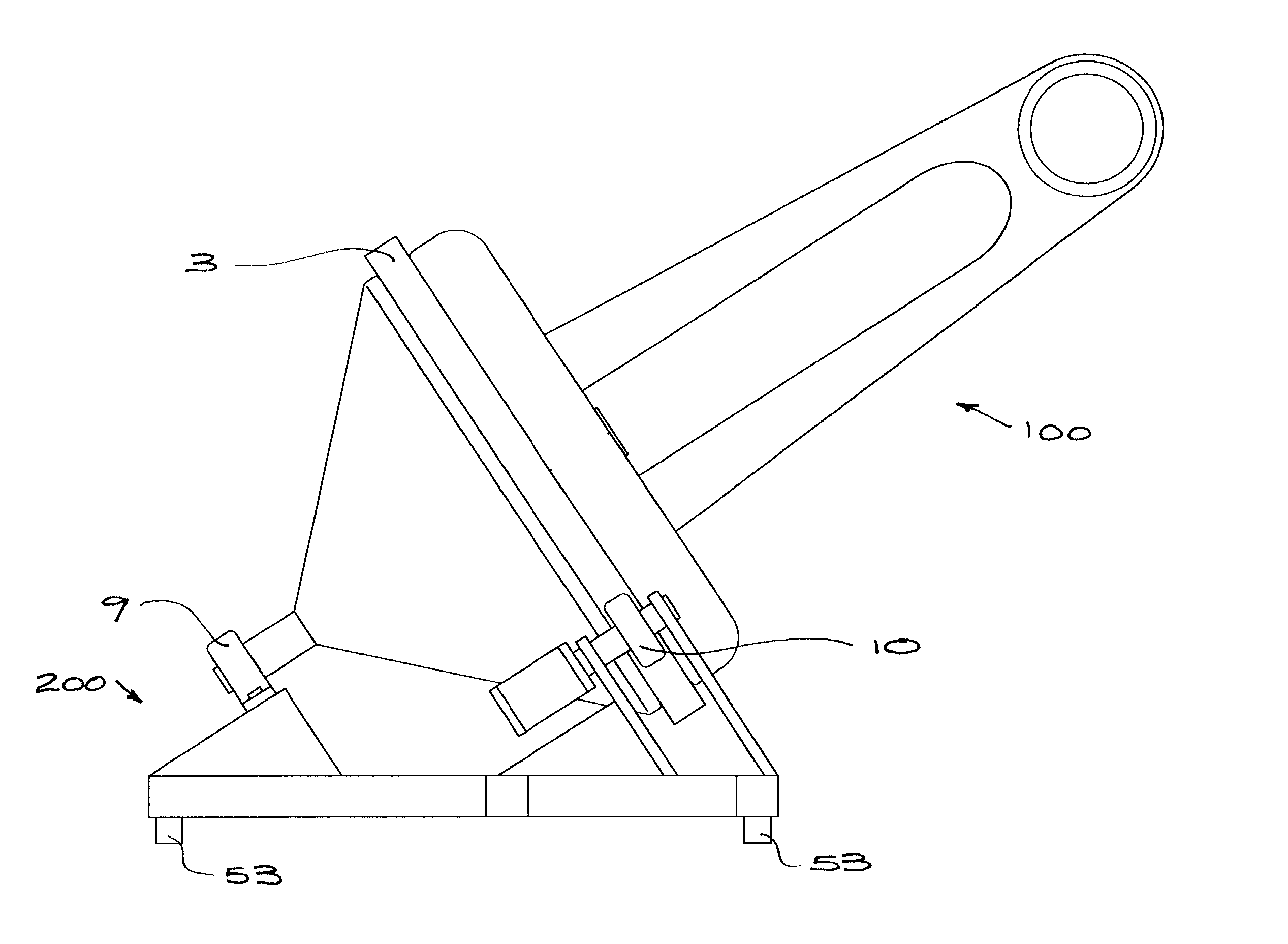
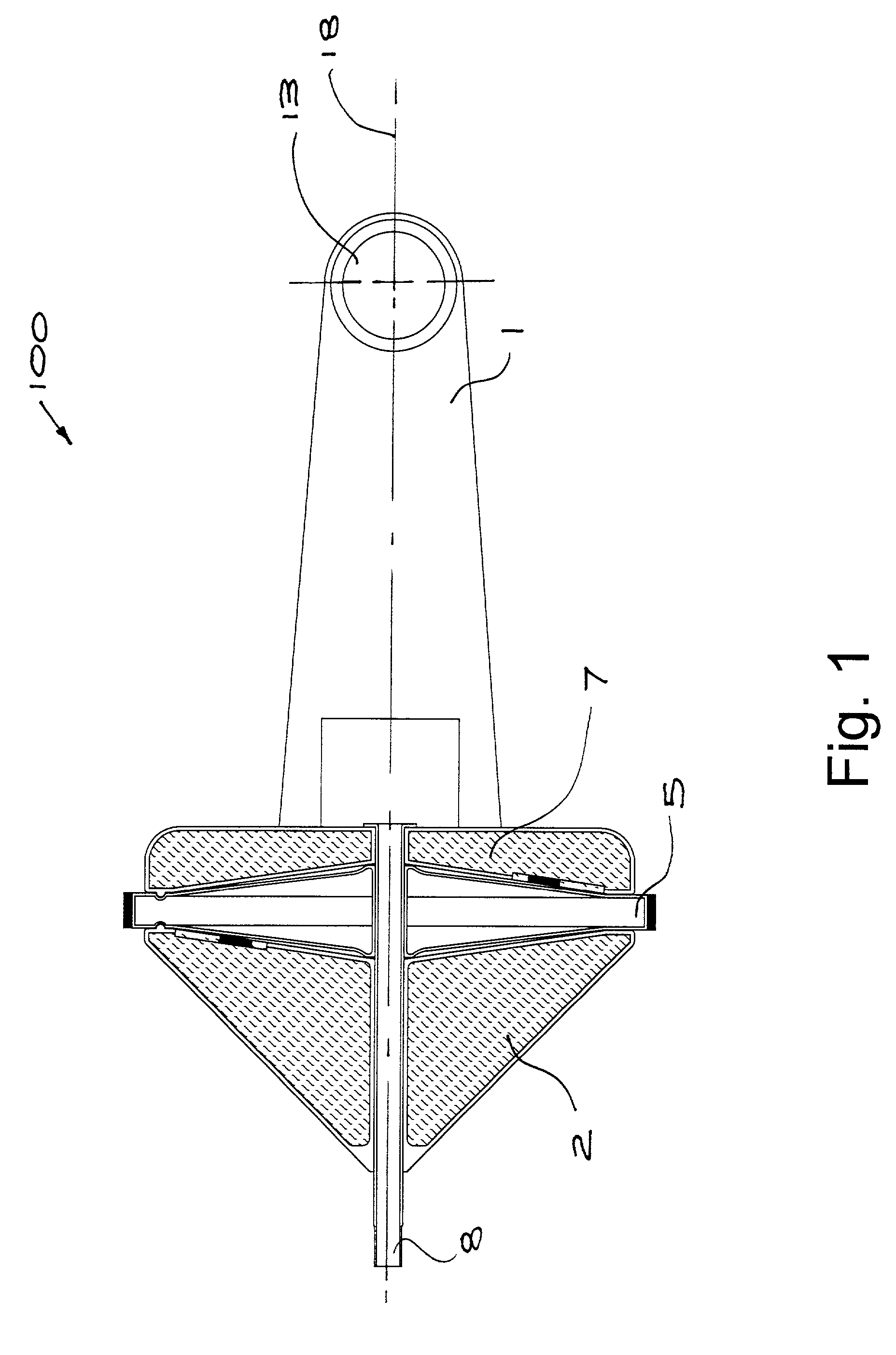
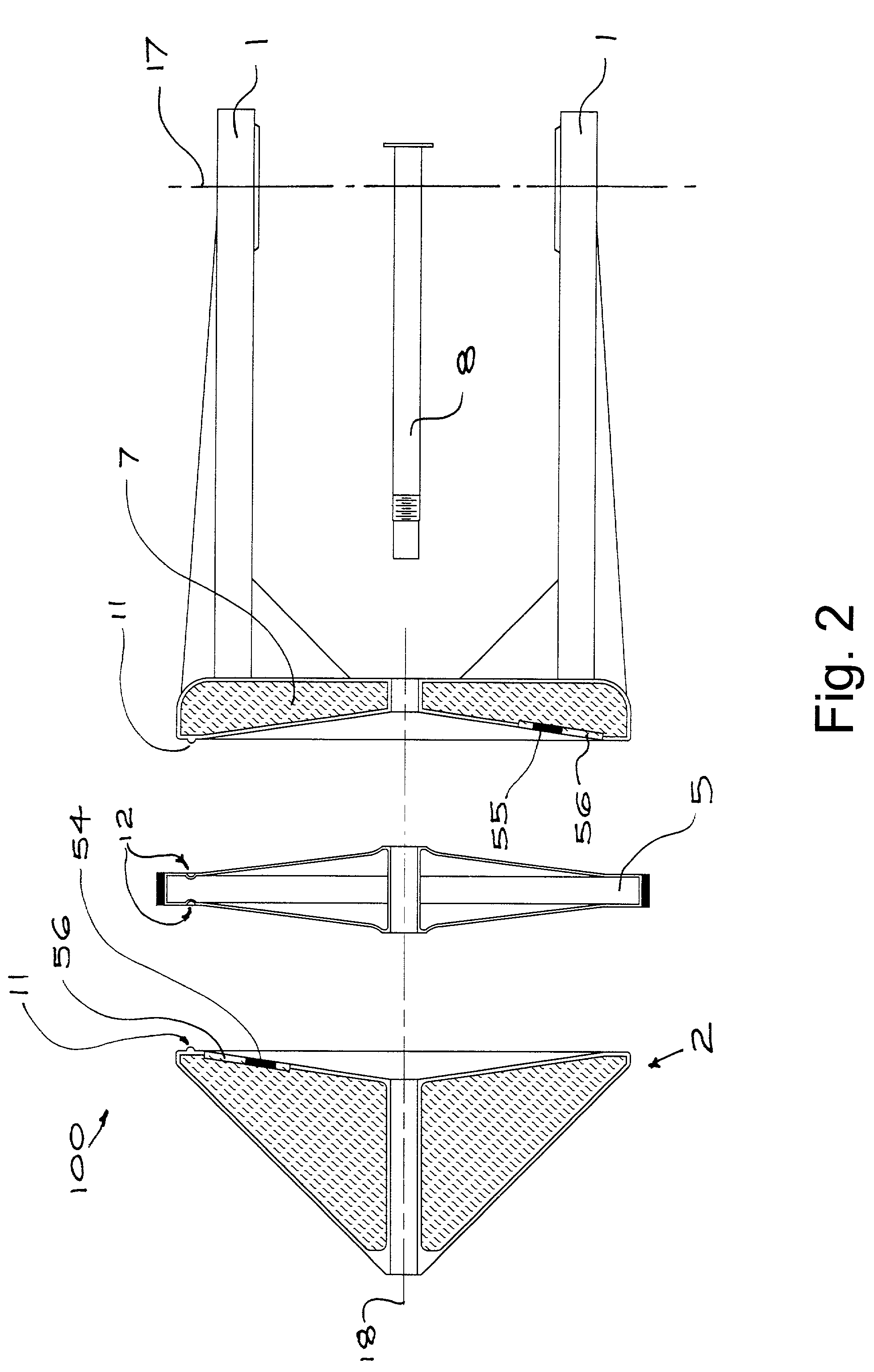
[0027] Referring to FIGS. 1 and 2, a fork mount 100 for a telescope is substantially symmetrical about axis 18 and includes two tines 1 connected by a hollow yoke 7 which is adapted to contain ballast material (indicated by the hatching on the drawing). The yoke 7 is fixed to one side of a drive wheel 5, the other side of which is fixed to a generally conical ballast container 2. Bearing apertures 13 are provided in the opposing tines 1 and define an axis 17, orthogonal to axis 18. Both the container 2 and yoke 7 are liquid tight and capable of holding any flowable ballast.

[0028] The container 2 and wheel 5 are adapted to be readily separable from the yoke 7. When separated (as shown in FIG. 2) ballast can be added or removed by means of closures 54, 55 in the container 2 and yoke 7 respectively. The closures 54, 55 are each formed in a membrane 56 to equalize atmospheric pressure between inside the vessel and the surrounding atmosphere. The container 2, wheel 5 and yoke 7 are clamp...