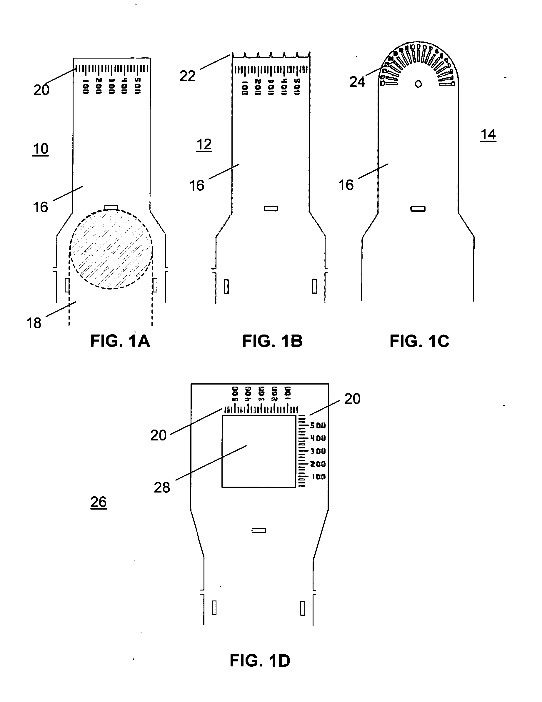
[0008] With specific reference to the various embodiments of the present invention, a first embodiment includes tools for sample measurements in which the
optical transparency of the
polymer film enables the sample being measured to be visualized through the film. The increased rigidity provided by the slight film curvature induced by wrapping the base of the film around the post allows easier measurements in, e.g., viscous liquids. The thinness of the film also allows it to be bent flat if it is pushed down against a flat surface. The softness and flexibility of the tool allow it to be used to push or dislodge from a substrate many soft, delicate, fragile samples like
protein crystals, cells, tissues, etc. without damaging them. This softness and flexibility also minimizes the chance of sample damage during incidental contact with the tool. The measuring tool can be placed right next to the sample being measured, for example, within the solution in which it resides, and with its orientation matching the orientation of the sample dimension to be measured. Consequently, the tool can provide accurate measurements under a much wider variety of sample conditions than a
microscope reticle, for example, which accurately measures dimensions only of surfaces perpendicular to the
optical axis and in the same medium as the outer surface of the lens.
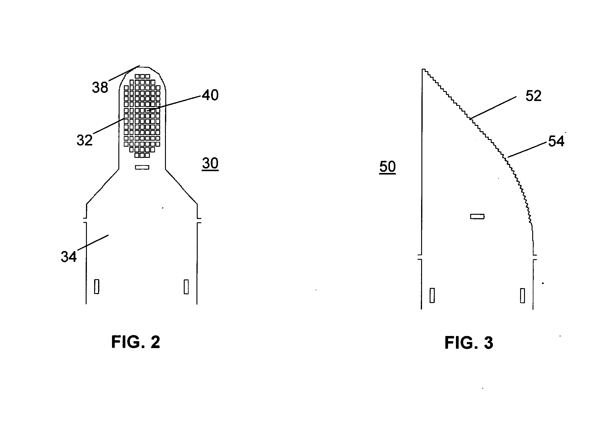
[0018] Another embodiment of the invention comprises tools for
sample temperature measurement. In many applications one wants to know the sample's temperature. For example, in cryocrystallography, the sample is placed in a cold gas (
nitrogen or
helium)
stream to keep it cold during X-ray data collection. The sample's temperature varies with how the gas flows are adjusted, with ambient conditions, and with the sample's position in the gas
stream. In this embodiment, the sample holders disclosed in the ‘315 application’ as well as any of the tools described here can be formed with an integral
thermocouple. The tool is again microfabricated from a
polymer like
polyimide or mylar. Two different
metal layers are patterned and deposited, so that they overlap at the tip, forming a
thermocouple junction. The metals may be deposited onto the
polymer film by, e.g.,
sputtering (to reduce heating of the film). Conventional
photoresist patterning and wet or
dry etching can be used to remove metal to form the final pattern. The extremely small size (10-20 micrometers) of the
thermocouple junction, the small cross-sectional area and therefore low thermal conductance of its leads, and the proximity of the junction to sample ensure accurate temperature measurements. The extremely low
thermal mass of the junction plus sample holder and the thin film design also ensures a very
rapid response in time to changes in temperature. In an alternative design, a
thermistor is employed instead of a thermocouple for the temperature sensor. The
thermistor can be fabricated by depositing and patterning on the
polyimide an
amorphous silicon layer. Provided that its lateral dimensions are small, the
thermistor can be made quite thin and thus have a small
thermal mass, without risk of breakage due to bending.

