Endodontic file and method

Inactive Publication Date: 2003-04-03
AHANI HESSAM
View PDF0 Cites 13 Cited by
  • Summary
  • Abstract
  • Description
  • Claims
  • Application Information

AI Technical Summary

Problems solved by technology

In the past, a major problem during a root canal procedure was identifying the length of each canals.
This was even more difficult because some teeth have four or even five canals.
However, using the Apex Locator is somewhat cumbersome.
In the back molar areas, space is limited and the clip 80 often blocks the vision of the dentist.
Furthermore, since the clip 80 is tight

Method used


Image

  • Endodontic file and method
  • Endodontic file and method
  • Endodontic file and method

Examples


Embodiment Construction

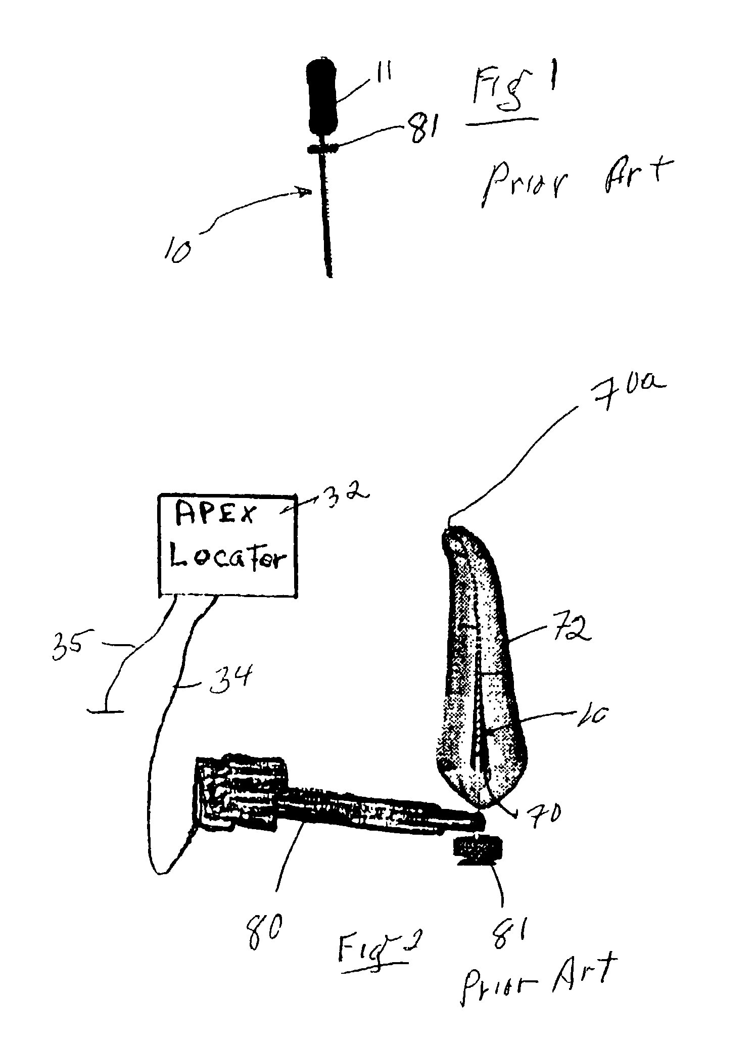
[0021] Referring now to FIGS. 1 and 2 of the drawings, and as previously indicated, the electronic device 32 may be part of an Apex Locator assembly. The ground conductor 35 extends from the electronic device 32 to a lip of a patient for grounding purposes. When the file 10 (e.g., prior art file 10 of FIG. 1) leaves the end 70a of the root canal 70 of the tooth 72, the circuit is closed and an indicator (e.g., a light or sound) is activated to inform the dentist that the file 10 has passed beyond end 70a. The circuit is closed by current passing through the gums of a patient, to the ground conductor 35 which is attached to a lip of the patient, and to the electronic device 32. Once the indicator goes off and is activated, a mental clip 80 is detached from prior art file 10 and stopper 81 (see FIG. 2) is pushed down to engage the tooth 72 (i.e., a reference point). The file 10 is removed from the canal 70 of the tooth 72, and the length of the canal 70 is the length of the file 10 fr...


PUM


Abstract

An endodontic file comprising a conductive shank, and a generally non-conductive portion circumscribing the conductive shank and longitudinally extending along the conductive shank. A method for conducting an endodontic procedure comprising providing an endodontic file assembly having a conductive shank electrically engaged to an electronic device for furnishing current to the conductive shank. A generally non-conductive portion circumscribes the conductive shank. The conductive shank including the non-conductive portion passes into a root canal of a tooth for conducting an endodontic procedure.

Description

[0001] This application claims the benefit of U.S. Provisional Application 60 / 325,669 filed Sep. 28, 2001.[0002] 1. Field of the Invention[0003] This invention is related to a dental instrument and method. More specifically, embodiments of the present invention provide an endodontic file and method for performing a root canal on a tooth.[0004] 2. Description of the Prior Art[0005] In the past, a major problem during a root canal procedure was identifying the length of each canals. This was even more difficult because some teeth have four or even five canals. To measure the length of a canal, a guess was made by measuring the root on an X-ray. Of course X-rays are often distorted and root canals often are shorter than the actual roots. After a guess was made by measuring the root on an X-ray, an endodontic file is placed in the tooth and another X-ray is taken. By doing this procedure, one can see how close one is to the end of the root.[0006] This procedure was made much easier by t...

Claims


Application Information

Patent Timeline
IPC IPC(8): A61C5/02
CPCA61C5/023A61C5/42
Inventor AHANI, HESSAM
Owner AHANI HESSAM
Why Eureka
Try Eureka