Piezoelectric/electrostrictive device

a piezoelectric/electrostrictive and electrode technology, applied in piezoelectric/electrostrictive/magnetostrictive devices, printing, other printing devices, etc., can solve the problems of low density of piezoelectric/electrostrictive layers, no investigation, and substrate interaction

Inactive Publication Date: 2003-09-18
NGK INSULATORS LTD
View PDF17 Cites 5 Cited by
  • Summary
  • Abstract
  • Description
  • Claims
  • Application Information

AI Technical Summary

Benefits of technology

[0012] The present inventors made an intensive study in order to attain the above object. As a result, the present inventors have found, as a new finding, that the densification of the piezoelectric / electrostrictive layer may be promoted even when the piezoelectric / electrostrictive material is coated on a substrate and then the resultant is subjected to a heat treatment in the case that a piezoelectric / electrostrictive material is a Ce-added PMN-PZT system composition, and further found that the densification of the piezoelectric layer may be attained without reducing the piezoelectric / electrostrictive properties as long as the Ce content in the piezoelectric / electrostrictive material is in a particular range. Moreover, the present inventors have found that when a PMN-PZT system composition wherein part of Pb is substituted with Sr and / or La, is allowed to contain Ce in a particular range, the improvement in piezoelectric / electrostrictive properties due to substitution with Sr or La becomes very striking. The present invention has been completed based on these findings.

Problems solved by technology

However, no investigation was made on a problem which a piezoelectric / electrostrictive material made of such a piezoelectric / electrostrictive ceramic composition, when laminated on a substrate, may give rise to interaction to the substrate, etc.
In fact, in a piezoelectric / electrostrictive device produced by laminating, on a substrate, a piezoelectric / electrostrictive material in which part of a PMN-PZT system composition is substituted with Sr, La or the like and then heat-treating the resulting laminate, the piezoelectric / electrostrictive layer has a low density owing to the restraint of the substrate, and there were problems in that the piezoelectric / electrostrictive layer gave a low flexural displacement, or, when a voltage was applied, the low-density portion of the layer gave rise to dielectric breakdown or short circuit.
Moreover, the composition per se had no sufficient piezoelectric / electrostrictive property.
In this piezoelectric device, however, an inorganic or organic adhesive need be used in adhering the piezoelectric part on the ceramic substrate; therefore, there were problems that the adhesive impaired the transmission of oscillation between the substrate and the piezoelectric layer, or the properties of the piezoelectric layer and the substrate were deteriorated since adhesive components penetrated thereinto.

Method used


Image

  • Piezoelectric/electrostrictive device
  • Piezoelectric/electrostrictive device
  • Piezoelectric/electrostrictive device

Examples


example 1

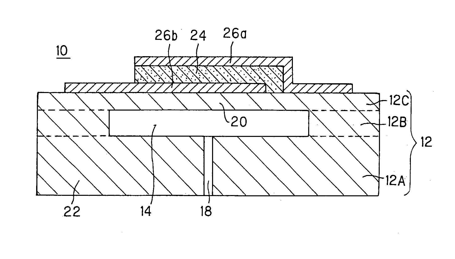
[0094] A platinum-made lower electrode [dimension: 1.2 mm.times.0.8 mm.times.3 .mu.m (thickness)] was formed, by screen printing, on a substrate whose diaphragm portion and fixing portion were, both made of Y.sub.2O.sub.3-stabilized ZrO.sub.2 [dimension of diaphragm portion: 1.6 mm.times.1.1 mm.times.10 .mu.m (thickness)]. A heat treatment at a temperature of 1300.degree. C. for 2 hours was carried out to integrate the electrode with the substrate.

[0095] Thereon was laminated, by screen printing, a piezoelectric material [dimension: 1.3 mm.times.0.9 mm.times.13 .mu.m (thickness)] made of a piezoelectric ceramic composition containing (1) 99.9% by mass of

(Pb.sub.0.999La.sub.0.001)(Mg.sub.1 / 3Nb.sub.2 / 3).sub.0.375Ti.sub.0.375Zr.s-ub.0.250O.sub.3

[0096] (wherein part of Pb was substituted with 0.1 mole % of La) (average particle diameter: 0.49 .mu.m, maximum particle diameter: 1.8 .mu.m) and (2) 0.100% by mass of CeO.sub.2.

[0097] Then, an atmosphere-controlling material having the same c...

examples 6 to 10

[0100] There were used piezoelectric materials each made of a piezoelectric ceramic composition having the same formulation as in Example 1 except that part of Pb was substituted with Sr according to a substitution ratio shown in Table 1. Other respects were the same as in Example 1, whereby piezoelectric devices were produced.

examples 16 to 25

[0102] There were used piezoelectric materials each made of a piezoelectric ceramic composition having a formulation in which part of Pb was substituted with La and Sr according to substitution ratios shown in Table 1 and the molar ratio (expressed in Table 1 simply as "A / B") of total mole of Pb, Sr and La to total mole of Mg, Nb, Zr and Ti was as shown in Table 1. The respective piezoelectric devices were produced in the same manner as in Example 1 except for the above mentioned.

Evaluation

[0103] (1) Examples 1 to 5 and Comparative Example 1

[0104] As shown in Table 1, the piezoelectric device of Comparative Example 1 showed a very low flexural displacement of 1.64 .mu.m. This device was composed of a ceramic composition obtained by adding Ce in an amount of 0.100% by mass (in terms of CeO.sub.2) to a PMN-PZT system composition in which Pb was not substituted with any of La and Sr.

[0105] In contrast, the piezoelectric devices of Examples 1 to 5 showed a large flexural displacements o...


PUM

PropertyMeasurementUnit
thicknessaaaaaaaaaa
thicknessaaaaaaaaaa
thicknessaaaaaaaaaa

Abstract

A piezoelectric / electrostrictive device comprising, on a ceramic-made substrate, at least one piezoelectric / electrostrictive layer made of a piezoelectric / electrostrictive ceramic composition and at least one pair of electrodes electrically connected to the piezoelectric / electrostrictive layer, characterized in that the piezoelectric / electrostrictive layer is made of a piezoelectric / electrostrictive ceramic composition containing a PbMg1 / 3Nb2 / 3O3-PbZrO3-PbTiO3 system composition wherein part of Pb is substituted with at least one kind selected from Sr and La, as a major component and Ce in an amount of 0.01 to 0.50% by mass in terms of CeO2 and that the piezoelectric / electrostrictive layer is solidly attached to the substrate directly or via part of the electrodes. The piezoelectric / electrostrictive device is superior in transmission of oscillation between the substrate and the piezoelectric / electrostrictive layer, produces a large displacement, and hardly gives rise to dielectric breakdown or short circuit.

Description

BACKGROUND OF THE INVENTION AND RELATED ART STATEMENT[0001] The present invention relates to a piezoelectric / electrostrictive device. More particularly, the present invention relates to a piezoelectric / electrostrictive device which has, on a substrate made of a ceramic, at least one piezoelectric / electrostrictive layer made of a piezoelectric / electrostrictive ceramic composition containing, as a major component, a PbMg.sub.1 / 3Nb.sub.2 / 3O.sub.3--PbZrO.sub.3--PbTiO.sub.3 system composition and at least one pair of electrodes electrically connected to the piezoelectric / electrostrictive layer.[0002] As an device capable of controlling a minute displacement in a submicron order, piezoelectric / electrostrictive devices have been known. In particular, a piezoelectric / electrostrictive device formed by laminating, on a substrate made of a ceramic, a piezoelectric / electrostri-ctive layer made of a piezoelectric / electrostrictive ceramic composition and an electrode layer to which a voltage is a...

Claims


Application Information

Patent Timeline
Patent Type & Authority Applications(United States)
IPC IPC(8): H01L41/083H01L41/09C04B35/49H01L41/187
CPCH01L41/0805Y10T29/42H01L41/1875H01L41/0973H10N30/1051H10N30/2047H10N30/8548
Inventor KASHIWAYA, TOSHIKATSUYAMAMOTO, KAZUHIROTAKAHASHI, MASAO
Owner NGK INSULATORS LTD
Why Eureka
Try Eureka