Self-positioning structure with adjustable frame body

a self-positioning structure and frame body technology, applied in the direction of safety guards, shutters/movable grilles, physical therapy, etc., can solve the problems of inaccurate angle of adjustment, small angle of rotation, and inconvenient adjustmen

Inactive Publication Date: 2003-12-18
CHEN TUNG I
View PDF3 Cites 8 Cited by
  • Summary
  • Abstract
  • Description
  • Claims
  • Application Information

AI Technical Summary

Problems solved by technology

However, the conventional structure has the following drawbacks: (a) Inconvenient in Operation: In this operation both hands of the user have to be employed and it is not convenient for injured person or sick person where one of the hands may not be conveniently used, (b) The angle of adjustment is not accurate: When the user has adjusted the rotating frame body to an appropriate angle, the wrench 16 has to be operated in order to position the structure, and a careless movement of the hand will cause the angle of adjustment being inaccurate, (c) The angle of rotating is small.

Method used


Image

  • Self-positioning structure with adjustable frame body
  • Self-positioning structure with adjustable frame body
  • Self-positioning structure with adjustable frame body

Examples


Embodiment Construction

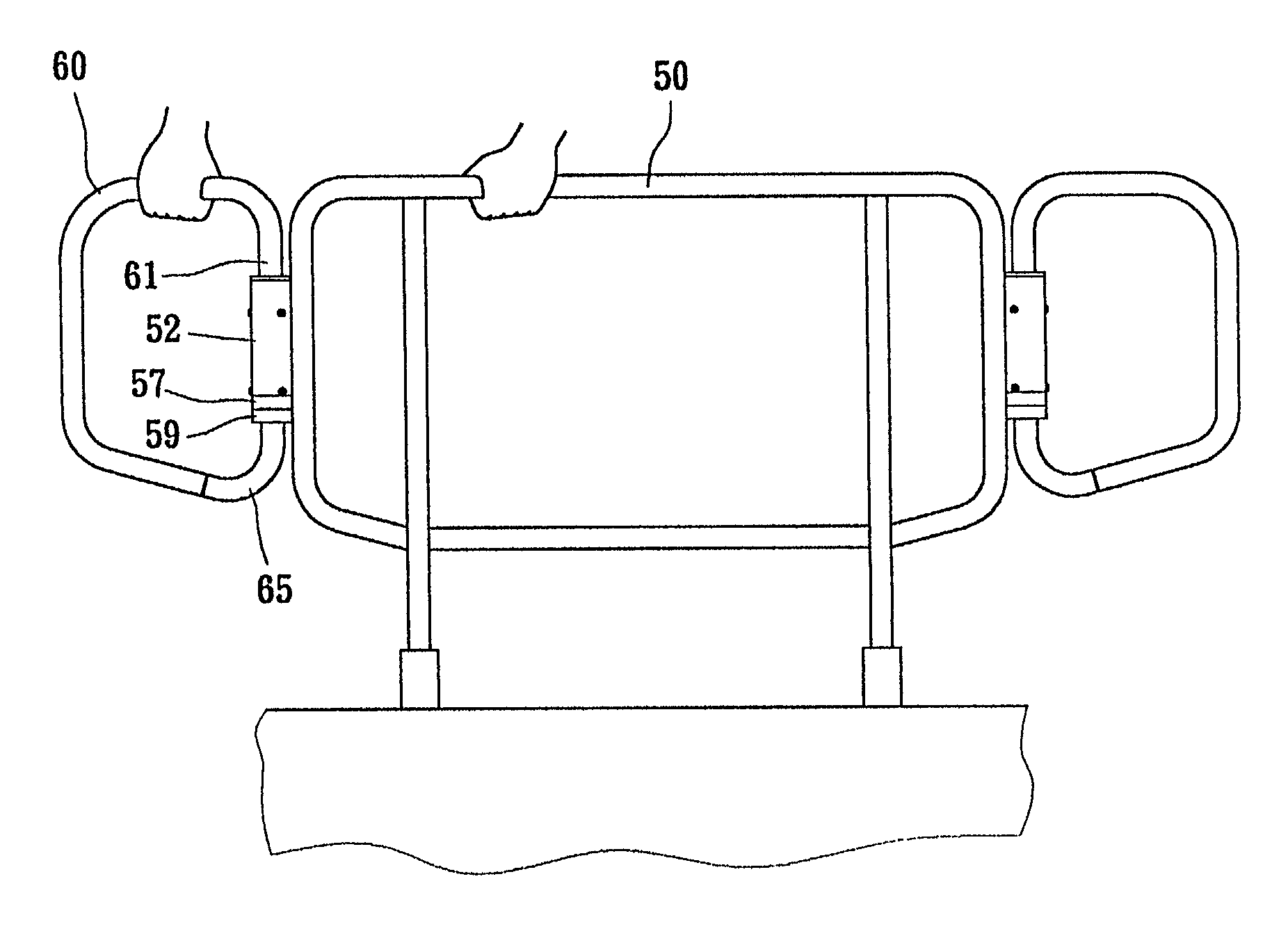
[0015] Referring to FIG. 3, there is shown a self-positioning structure with adjustable frame body comprising a main frame body 50 and a rotating frame body 60 pivotally mounted with each other. The main frame body 50 is extended downwardly for the mounting of a fixing rod 51. The rotating frame body 60 is rotatable or positioned with respect to the main frame body 50.

[0016] Referring to FIGS. 3 and 4, the main frame 50 corresponding to one lateral side of the rotating body 60 is provided with a hollow pivotal sleeve 52. The upper section of the interior of the pivotal sleeve 52 is mounted with a pivotal shaft 55 with a bolt 53. The top end of the pivotal shaft 55 is protruded with a resisting edge 56 which can resist the top edge of the pivotal sleeve 52. The bottom end of the pivotal sleeve 52 makes use of a bolt 54 to mount a teethed sleeve 57 which has been inserted into the interior thereof. The bottom face of the teethed sleeve 57 is formed into a cavity 58 and the bottom end ...


PUM


Abstract

A self-positioning structure with adjustable frame body is disclosed. The structure comprises a main frame body and a rotating body pivotally mounted to each other, characterized in that a pivotal sleeve is mounted to the main frame body and the upper section of the interior of the pivotal sleeve is a pivotal shaft for pivoting the rotating frame body, and the bottom end of the pivotal sleeve is mounted with a teethed sleeve inserted to the interior thereof, one end of the rotating body is downwardly formed into an extension section for inserting into the pivotal shaft, and the extension section is inserted beyond one end of the pivotal shaft and is mounted with a teethed block, a compression spring is supported by the teethed block and the bottom end of the pivotal shaft, and the teethed block is in engagement with the teethed sleeve, thereby a self-positioning structure with accurate angle of positioning angle is obtained.

Description

[0001] (a) Field of the Invention[0002] The present invention relates to structure of a self-positioning structure, and in particular to a structure where the frame body can be conveniently positioned.[0003] (b) Description of the Prior Art[0004] Conventional self-positioning structure is shown in FIGS. 1 and 2. In operation, a wrench 16 has to be turned upward so that the teethed block 25 is disengaged with the teethed-face 15, and the rotating frame 20 can be adjusted. When the rotating frame 20 has rotated to the desired angle, the wrench 16 has to be placed downward, and the teethed block 25 and the teethed-face 15 are in engagement again, so as to achieve the adjustment of the rotating frame body.[0005] However, the conventional structure has the following drawbacks: (a) Inconvenient in Operation: In this operation both hands of the user have to be employed and it is not convenient for injured person or sick person where one of the hands may not be conveniently used, (b) The an...

Claims


Application Information

Patent Timeline
Patent Type & Authority Applications(United States)
IPC IPC(8): E06B9/06E06B11/08
CPCE06B11/08E06B2009/002E06B11/085
Inventor CHEN, TUNG-I
Owner CHEN TUNG I
Why Eureka
Try Eureka