
Airbag for head-protecting airbag device

a technology for airbags and head protection, which is applied in the direction of pedestrian/occupant safety arrangements, vehicular safety arrangments, vehicle components, etc., and can solve problems such as reducing the protection area in the front-rear direction

Active Publication Date: 2004-05-27
TOYODA GOSEI CO LTD
View PDF4 Cites 20 Cited by
  • Summary
  • Abstract
  • Description
  • Claims
  • Application Information

AI Technical Summary

Benefits of technology

The present invention relates to an airbag for head-protecting airbag device that can generate a great tension along the front-rear direction in its lower edge upon deployment, while securing a wide protection area in the front-rear direction for protecting vehicle occupants properly. The airbag includes a gas admissive portion and a non-admissive portion, with the gas admissive portion including an inflatable shielding portion for covering the vehicle's inner side of the windows upon deployment of the airbag. The non-admissive portion includes a plurality of protection portions juxtaposed along the front-rear direction of the vehicle as the airbag is completely inflated. The airbag is normally folded in an upper edge of windows inside a vehicle, and the front protection portion is housed in a front pillar which is extended from a roof side rail obliquely down and forward. The rear protection portion includes a plurality of horizontal chambers arranged along the front-rear direction and juxtaposed in the vertical direction. The airbag is designed to generate a tension along the front-rear direction in its lower edge, while securing a wide protection area in the front-rear direction for protecting vehicle occupants properly.

Problems solved by technology

With this configuration, although a great tension along the front-rear direction is exerted in the lower edge of the airbag upon inflation, a rear lower edge of the rear protection portion is tensed forward of the vehicle, which reduces the protection area in the front-rear direction.

Method used


Image

  • Airbag for head-protecting airbag device
  • Airbag for head-protecting airbag device
  • Airbag for head-protecting airbag device

Examples


Embodiment Construction

[0031] A preferred embodiment of the present invention is described below with reference to the accompanying drawings. However, the invention is not limited to the embodiments disclosed herein. All modifications within the appended claims and equivalents relative thereto are intended to be encompassed in the scope of the claims.

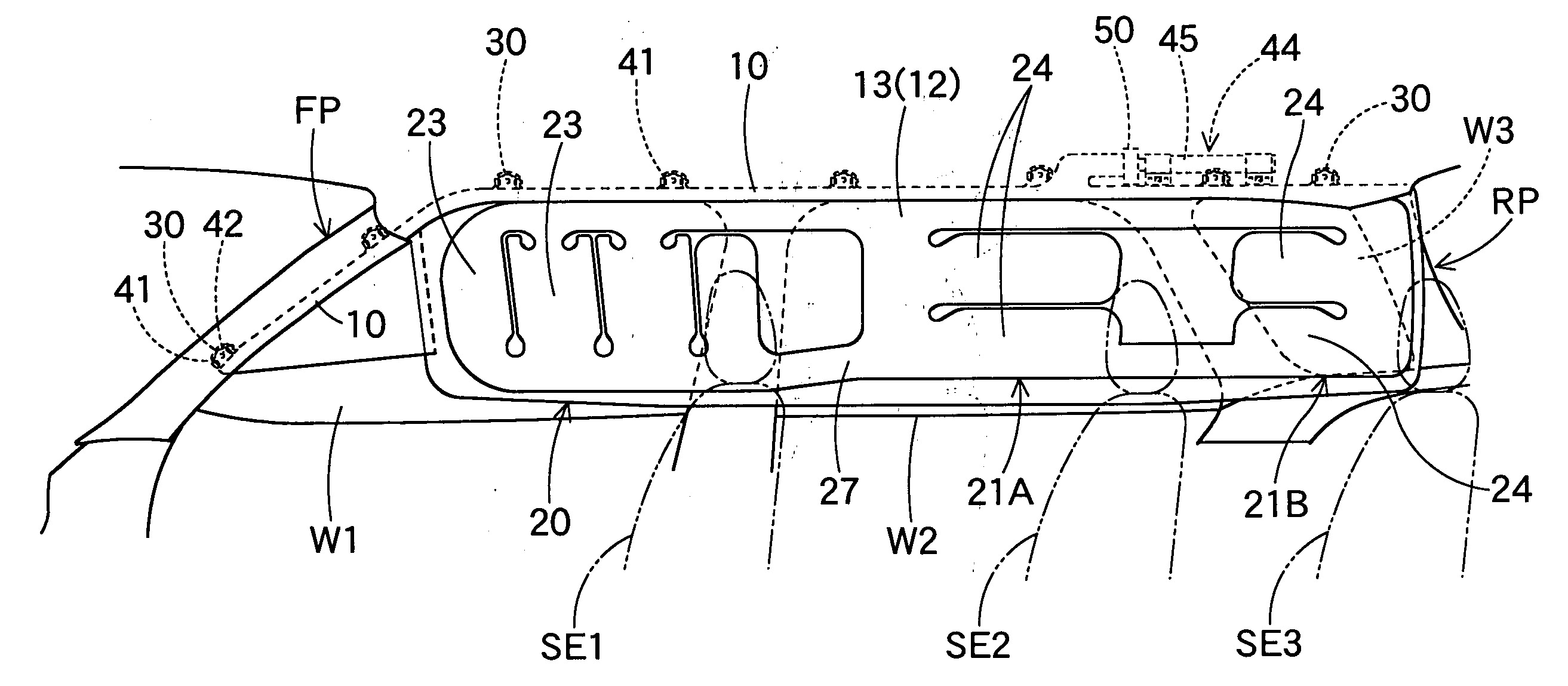
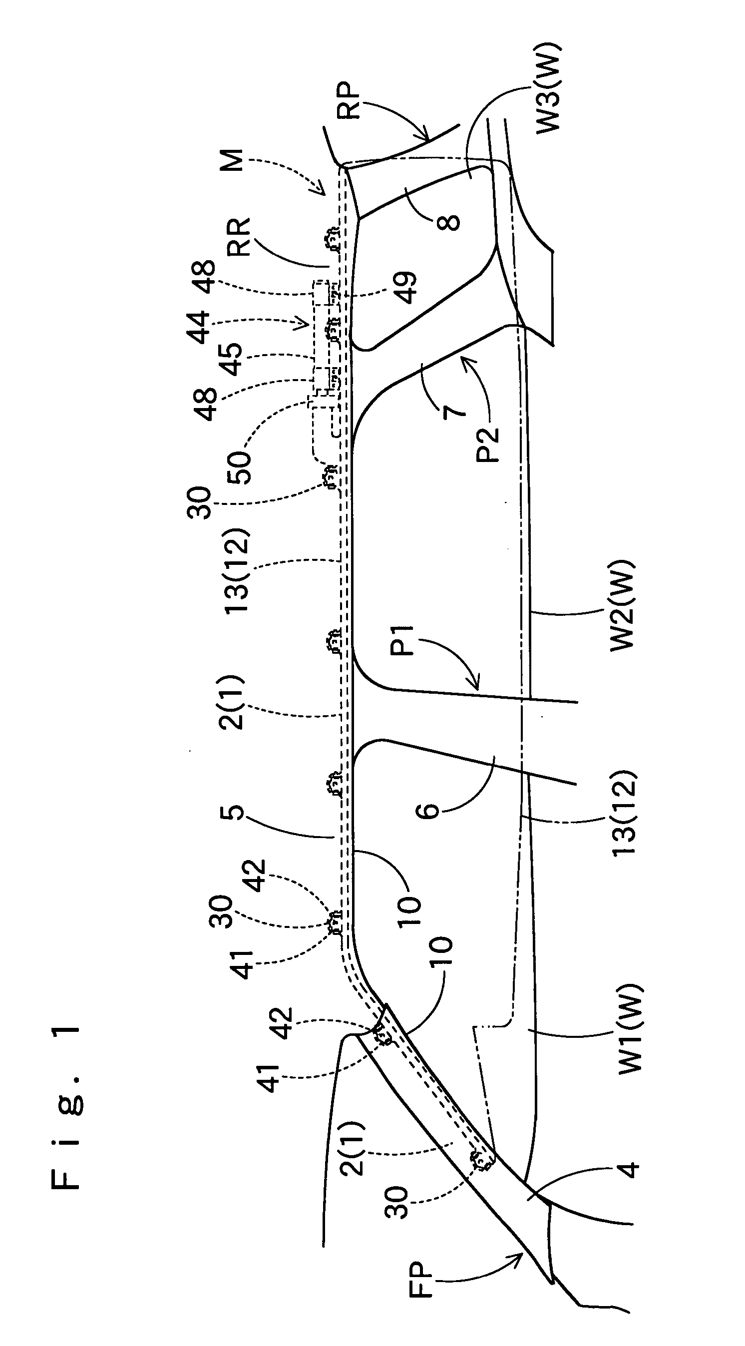
[0032] Referring to FIG. 1, an airbag 12 according to the present invention is employed in a head-protecting airbag device M mountable on a vehicle V. The airbag 12 is normally folded and housed in lower edges of a front pillar FP and a roof side rail RR in the upper periphery of doors and windows W (W1, W2 and W3) inside the vehicle.

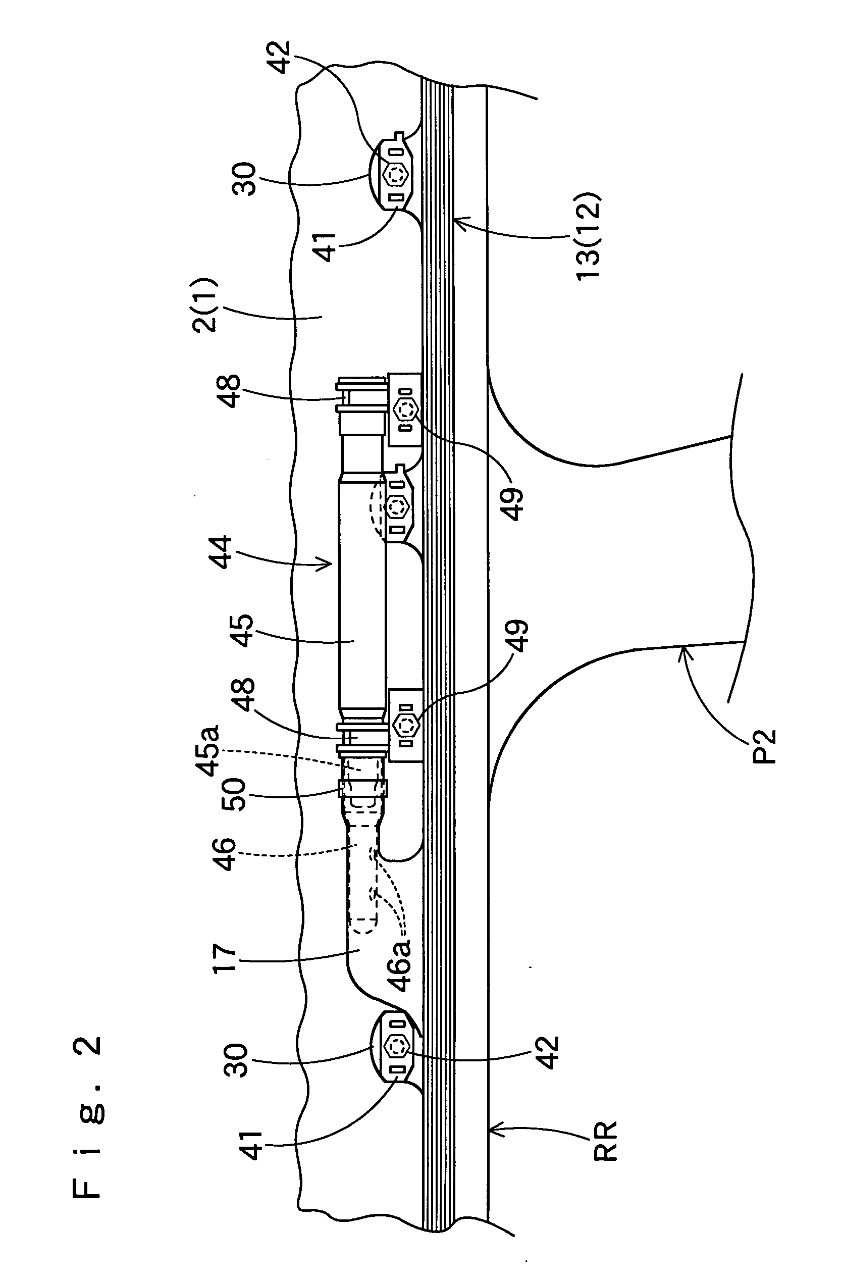
[0033] The airbag device M includes the airbag 12, an inflator 44, mounting brackets 41, 48, and an airbag cover 10.

[0034] As shown in FIG. 1, the airbag cover 10 is constituted by the lower edges of each of a pillar garnish 4 arranged on the front pillar FP and a roof head lining 5 arranged on the roof side rail RR. The airbag c...


PUM


Abstract

An airbag for head-protecting airbag device according to the present invention is normally folded and housed in an upper edge of windows including a front pillar. The airbag includes a gas admissive portion. An inflatable shielding portion of the gas admissive portion includes a plurality of protection portions, at least one of which located toward front end of the airbag acts as front protection portion, and remaining protection portions located rearward of the front protection portion act as rear protection portions. The front protection portion includes a plurality of vertical chambers juxtaposed along the front-rear direction of the vehicle, and each of the vertical chambers is arranged vertically. The rear protection portions include a plurality of horizontal chambers juxtaposed in the vertical direction, and each of the horizontal chambers is arranged along the front-rear direction of the vehicle.

Description

[0001] The present application claims priority from Japanese Patent Application No. 2002-343782 filed on Nov. 27, 2002, the entirety of which is hereby incorporated into the present application by this reference.[0002] 1. Field of the Invention[0003] The present invention relates to an airbag for head-protecting airbag device which is normally folded and housed in an upper edge of windows in the interior of vehicle including a front pillar sloping down forward, and deployable to cover the interior of the windows upon inflow of inflation gas.[0004] 2. Description of Related Art[0005] In the prior art, Japanese Patent Laid-Open No. 2000-335351 is illustrative of an airbag for head-protecting airbag device which includes a plurality of protection portions juxtaposed along the vehicle's front-rear direction as deployed.[0006] In this airbag, both of a front protection portion arranged forward and a rear protection portion arranged rearward include a plurality of horizontal inflatable ch...

Claims


Application Information

Patent Timeline
Patent Type & Authority Applications(United States)
IPC IPC(8): B60R21/20B60R21/16B60R21/232B60R21/233
CPCB60R21/213B60R21/232B60R21/2338B60R2021/23386B60R21/261B60R2021/23316B60R21/2346
Inventor OGATA, TETSUYA
Owner TOYODA GOSEI CO LTD
Features
  • Generate Ideas
  • Intellectual Property
  • Life Sciences
  • Materials
  • Tech Scout
  • Unparalleled Data Quality
  • Higher Quality Content
  • 60% Fewer Hallucinations
Learn More