Supercharge Your Innovation With Domain-Expert AI Agents!

Loading drive mechanism and disk unit provided with the loading drive mechanism

Inactive Publication Date: 2004-07-15
MITSUMI ELECTRIC CO LTD
View PDF4 Cites 5 Cited by
  • Summary
  • Abstract
  • Description
  • Claims
  • Application Information

AI Technical Summary

Problems solved by technology

Therefore, the number of parts are necessarily increased, and the assembling operation is also complicated.

Method used


Image

  • Loading drive mechanism and disk unit provided with the loading drive mechanism
  • Loading drive mechanism and disk unit provided with the loading drive mechanism
  • Loading drive mechanism and disk unit provided with the loading drive mechanism

Examples


Embodiment Construction

[0085] The preferred embodiments of a disc drive according to the present invention are described below with reference to the appended drawings.

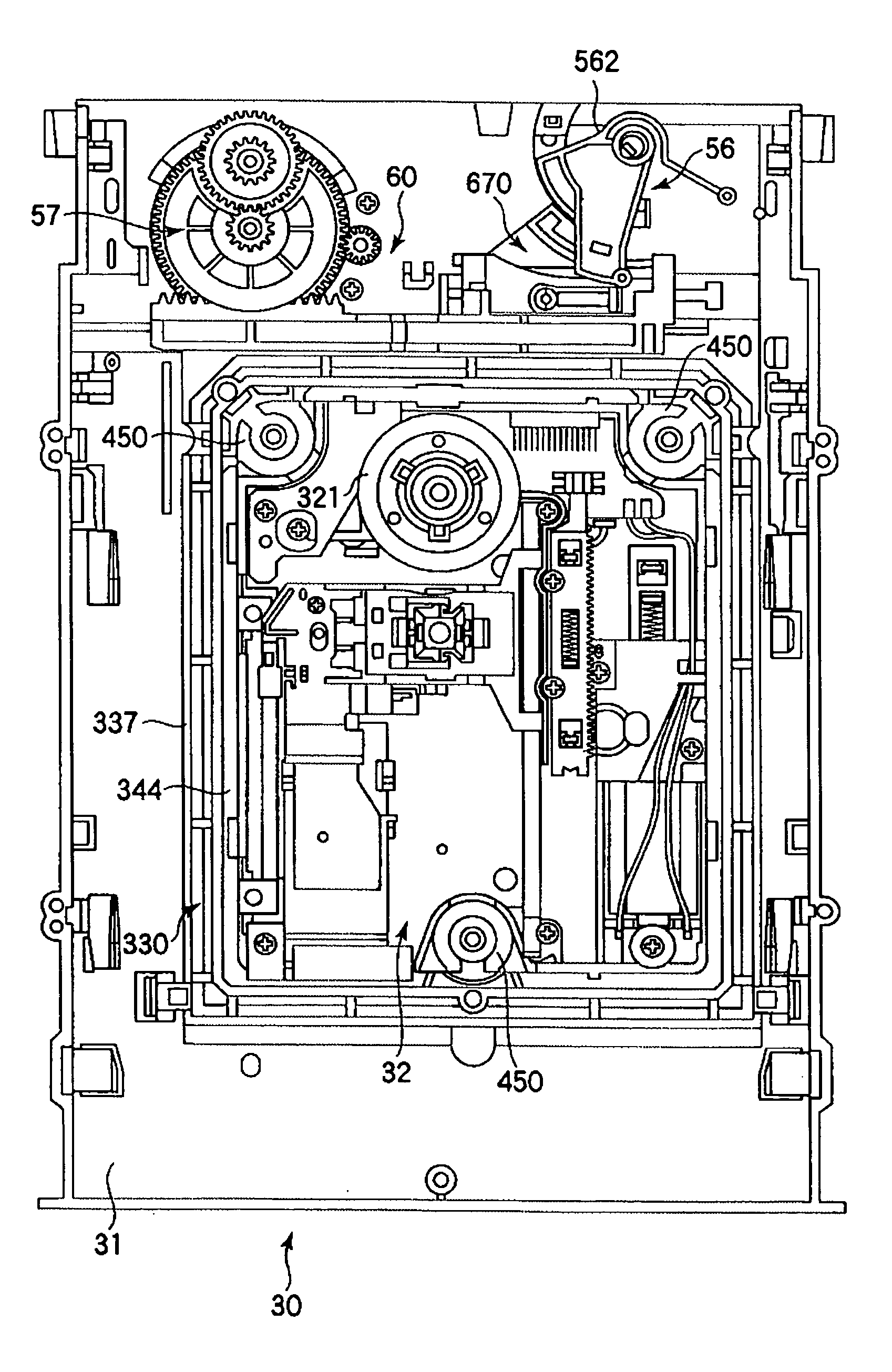
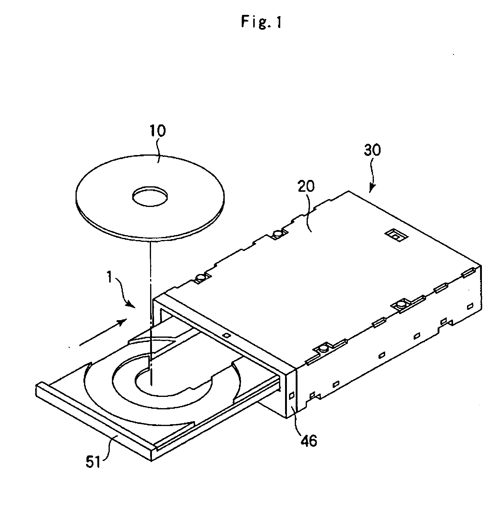
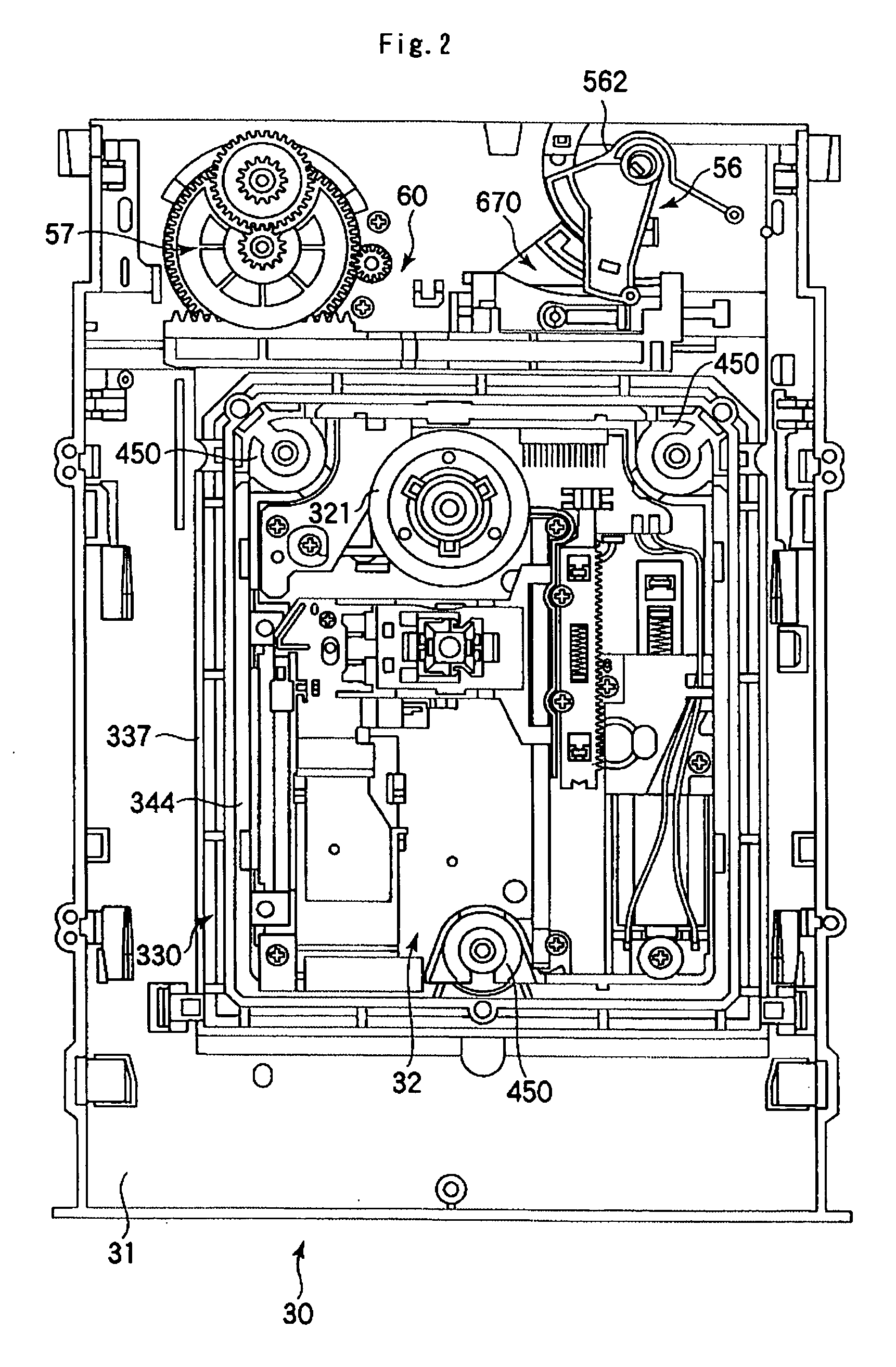
[0086] FIG. 1 is a perspective view showing the overall structure of a disc drive of the present invention, and FIG. 2 is a top view of a main unit of the disc drive.

[0087] As shown in FIG. 1, the disc drive 1 is an optical disc drive which carries out playback (reproducing) or recording / playback operation on a disc 10 such as a CD, DVD or the like. The disc drive 1 is generally constructed from a main unit 30 (see FIG. 2) housed in a casing 20, and a disc tray 51 for conveying the disc 10 which is movable in the forward and backward directions (horizontal direction).

[0088] As shown in FIG. 2, the main unit 30 includes a printed circuit board (not shown in the drawings), and a chassis 31 provided on the printed circuit board. Further, as was described above, the main unit 30 is housed in the casing 20 made from a thin metal plate.

[0089] Furt...


PUM


Abstract

It is an object to provide a loading drive mechanism by which it is possible to manually move a disc tray smoothly, and by which the number of parts can be made relatively small and assembling operation can be carried out easily, and a disc drive provided with the loading drive mechanism. The disc drive 1 comprises a chassis 31, reproducing means for reproducing information recorded in a disc, and a disc tray 51 for holding the disc which is movable between a disc reproducing position and a disc ejection position, the disc drive further comprising a loading drive mechanism 57 for driving the disc tray 51, wherein the loading drive mechanism comprises a rack gear 540 provided on the disc tray 51 and having at least a part thereof which extends linearly along the longitudinal direction of the disc tray 51, a guide groove 550 which is arranged along the rack gear 540, and a second gear 640 which is a drive gear which meshes with the rack gear 540, a second rotation shaft 315 for rotatably mounting the drive gear 640, wherein the rotation shaft 315 engages with the guide groove 550 of the disc tray 51.

Description

[0001] The present invention relates to a loading drive mechanism for a disc tray provided in a disc drive equipped with the disc tray, and a disc drive equipped with the loading drive mechanism.DESCRIPTION OF THE PRIOR ART[0002] FIG. 51 is a bottom view of a disc tray used in a prior art disc drive. FIGS. 53(a) and (b) are respectively top plan views of a main unit of the prior art disc drive, in which FIG. 53(a) shows a state that a sector gear provided in the main body is at a first position and FIG. 53(b) shows a state that the sector gear is at a second position.[0003] As shown in FIG. 51, a disc tray 730 of the prior art disc drive includes a rack gear 738 which meshes with a second gear provided in a main unit 740 described later when the disc tray is moving, and a guide groove 731 which engages with an engagement pin 755 provided in a sector gear 754 of a cam mechanism described later. As shown in FIG. 51, the guide groove 731 includes a first guide groove 732 positioned at ...

Claims


Application Information

Patent Timeline
IPC IPC(8): G11B17/056G11B17/04
CPCG11B17/056
Inventor NAKAMURA, MITSUNORIARAI, TOYOKAZUMANABE, SATORU
Owner MITSUMI ELECTRIC CO LTD
Features
  • R&D
  • Intellectual Property
  • Life Sciences
  • Materials
  • Tech Scout
  • Unparalleled Data Quality
  • Higher Quality Content
  • 60% Fewer Hallucinations
Learn More