Impeller

Active Publication Date: 2005-01-06
EBARA CORP
View PDF13 Cites 6 Cited by
  • Summary
  • Abstract
  • Description
  • Claims
  • Application Information

AI Technical Summary

Benefits of technology

[0005] The present invention has been made in view of the above drawbacks of the prior art. It is, therefore, an object of the present invention to pro

Problems solved by technology

Accordingly, when each one of the main plates 110 is to be raised, an adjacent main plate is also r

Method used


Image

  • Impeller
  • Impeller
  • Impeller

Examples


Example

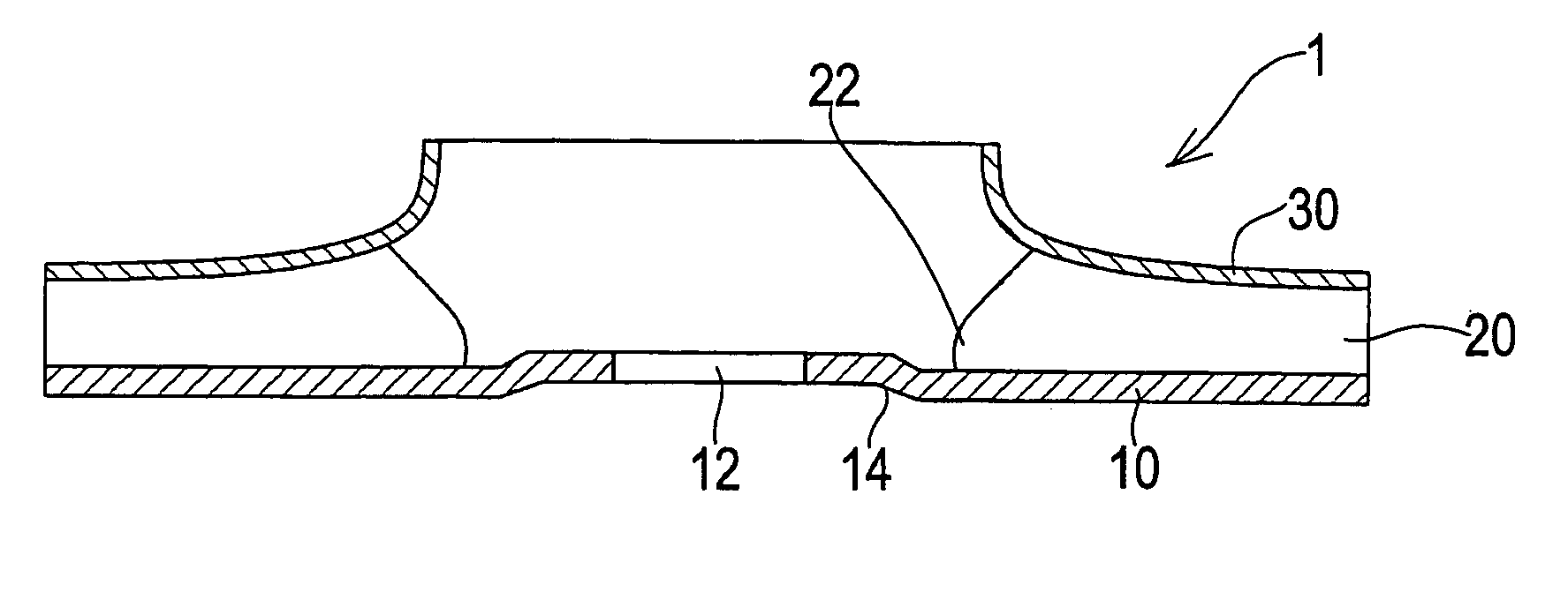
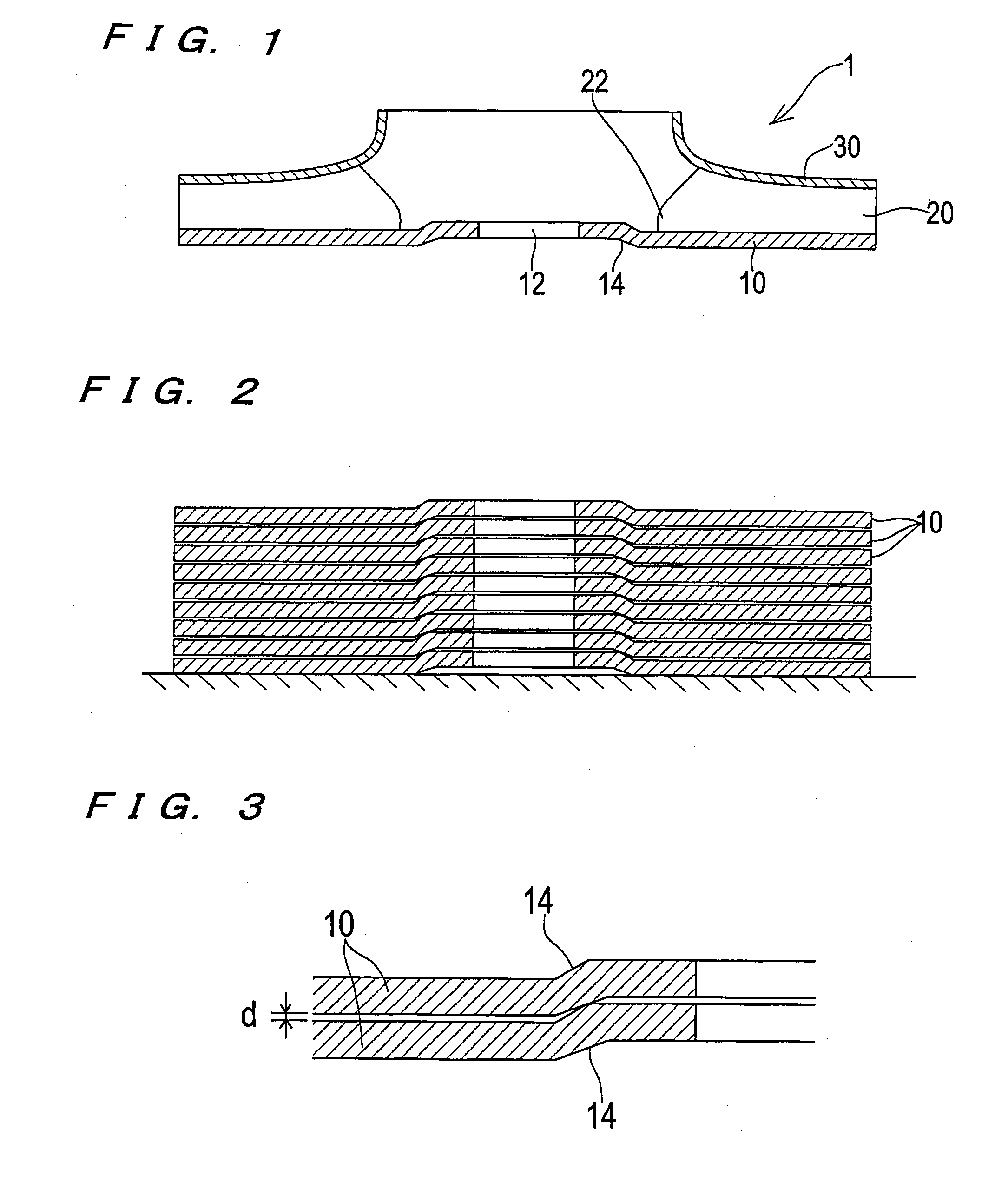
[0018] An impeller according to an embodiment of the present invention will be described below in detail with reference to FIGS. 1 through 3. FIG. 1 is a vertical cross-sectional view showing an impeller according to an embodiment of the present invention, FIG. 2 is a schematic view showing a state in which main plates of impellers according to an embodiment of the present invention are piled on one another, and FIG. 3 is a partial enlarged view of FIG. 2.

[0019] As shown in FIG. 1, an impeller 1 has a main plate 10, blades 20 joined to the main plate 10, and a side plate 30 having a suction port. A sheet metal material such as stainless steel is die-cut into a disk-like shape to form the main plate 10. A boss hole 12 is formed in a central portion of the main plate 10 for attaching a boss which engages with a pump shaft to the boss hole. Drawing is carried out by a press to form a step portion 14, which is raised upward, around the boss hole 12.

[0020] Since the step portion 14 is ...


PUM

PropertyMeasurementUnit
Lengthaaaaaaaaaa
Lengthaaaaaaaaaa

Abstract

An impeller (1) according to the present invention has a disk-like main plate (10), a blade (20) joined to the main plate, and a side plate (30) having a suction port. A boss hole (12) is formed in a central portion of the main plate for attaching a boss which engages with a pump shaft to the boss hole. A step portion (14) is formed around the boss hole, which is formed in the main plate, by drawing.

Description

TECHNICAL FIELD [0001] The present invention relates to an impeller used for a pump or the like, and more particularly to an impeller manufactured by press-forming a sheet metal material. BACKGROUND ART [0002] Impellers used for a pump or the like are mostly manufactured by welding parts, into which a sheet metal material is press-formed, with an automatic welding machine. FIG. 5 is a schematic cross-sectional view of a conventional impeller. As shown in FIG. 5, the impeller 100 is composed of a disk-like main plate 110, blades 120 joined to the main plate 110, and a side plate 130 having a suction port. [0003] A sheet metal material is die-cut and press-formed to produce the blades 120 of the impeller 100, and then the blades 120 of the impeller 100 are joined to the main plate 110 by welding. However, in the conventional impeller, as shown in FIG. 5, radially inner end portions 122 of the blades 120 which are joined to the main plate 110 are so sharp that a large load is applied t...

Claims


Application Information

Patent Timeline
IPC IPC(8): F04D1/06F04D29/20F04D29/22F04D29/24F04D29/28F04D29/62
CPCF04D1/066F04D29/2227F04D29/20F04D29/026F04D1/06F05D2300/171F05D2230/54
Inventor KAJIWARA, KENICHIKUROIWA, SOUMORI, KIKUICHIKUNIMASA, KOICHI
Owner EBARA CORP
Why Eureka
Try Eureka