Image reading apparatus

Inactive Publication Date: 2005-09-22
KK TOSHIBA +1
View PDF14 Cites 3 Cited by
  • Summary
  • Abstract
  • Description
  • Claims
  • Application Information

AI Technical Summary

Benefits of technology

[0005] An object of the present invention is to shorten a warming-up time of a scanner at the t

Problems solved by technology

In the method in which power to a scanner is shut off, an initial operation of the scanner must be carried out after returning from the power saving mode, and it takes long time for warming-up.
Further, in the method i

Method used


Image

  • Image reading apparatus
  • Image reading apparatus
  • Image reading apparatus

Examples


Embodiment Construction

[0016] An embodiment of the present invention will be described in detail hereinafter with reference to the drawings.

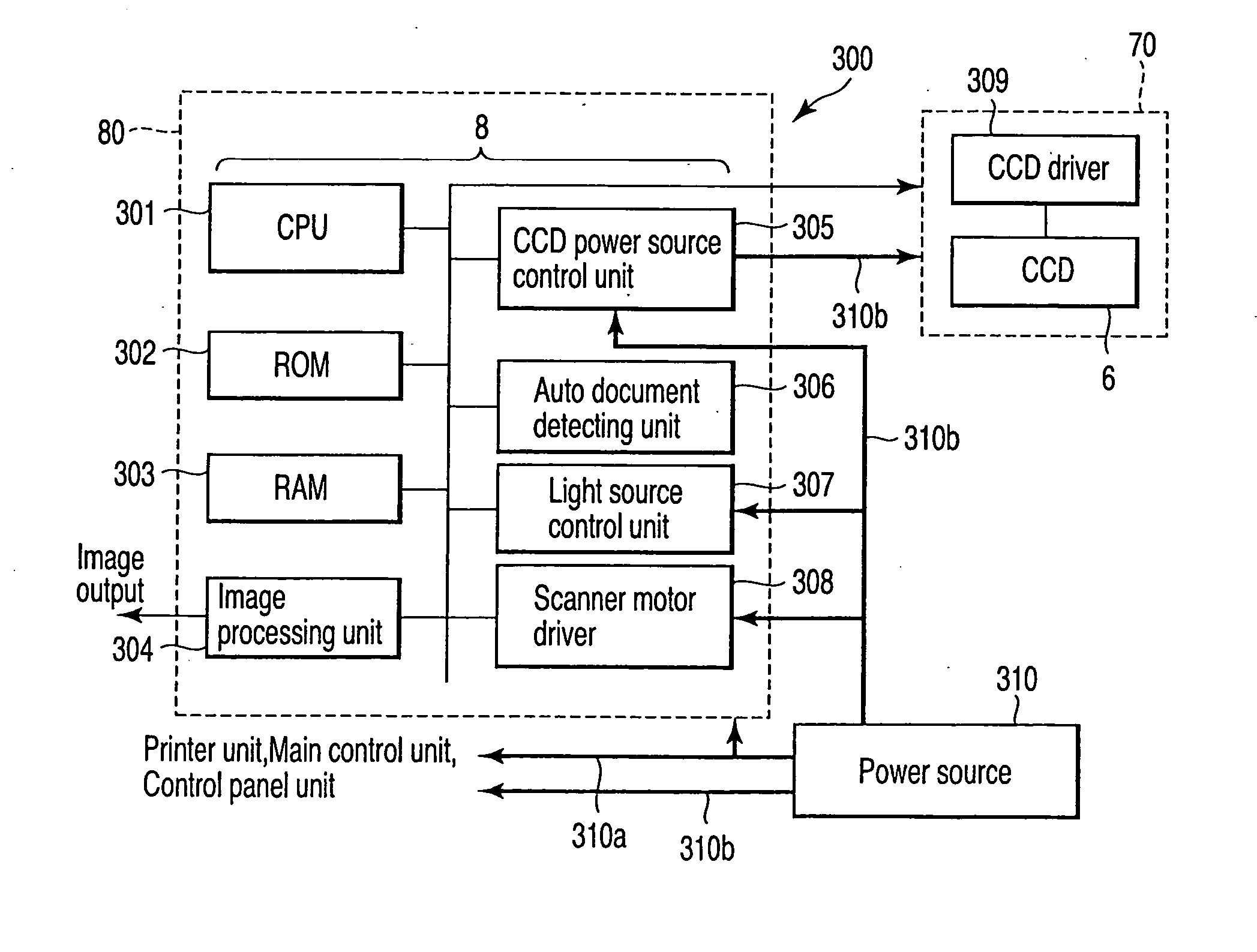
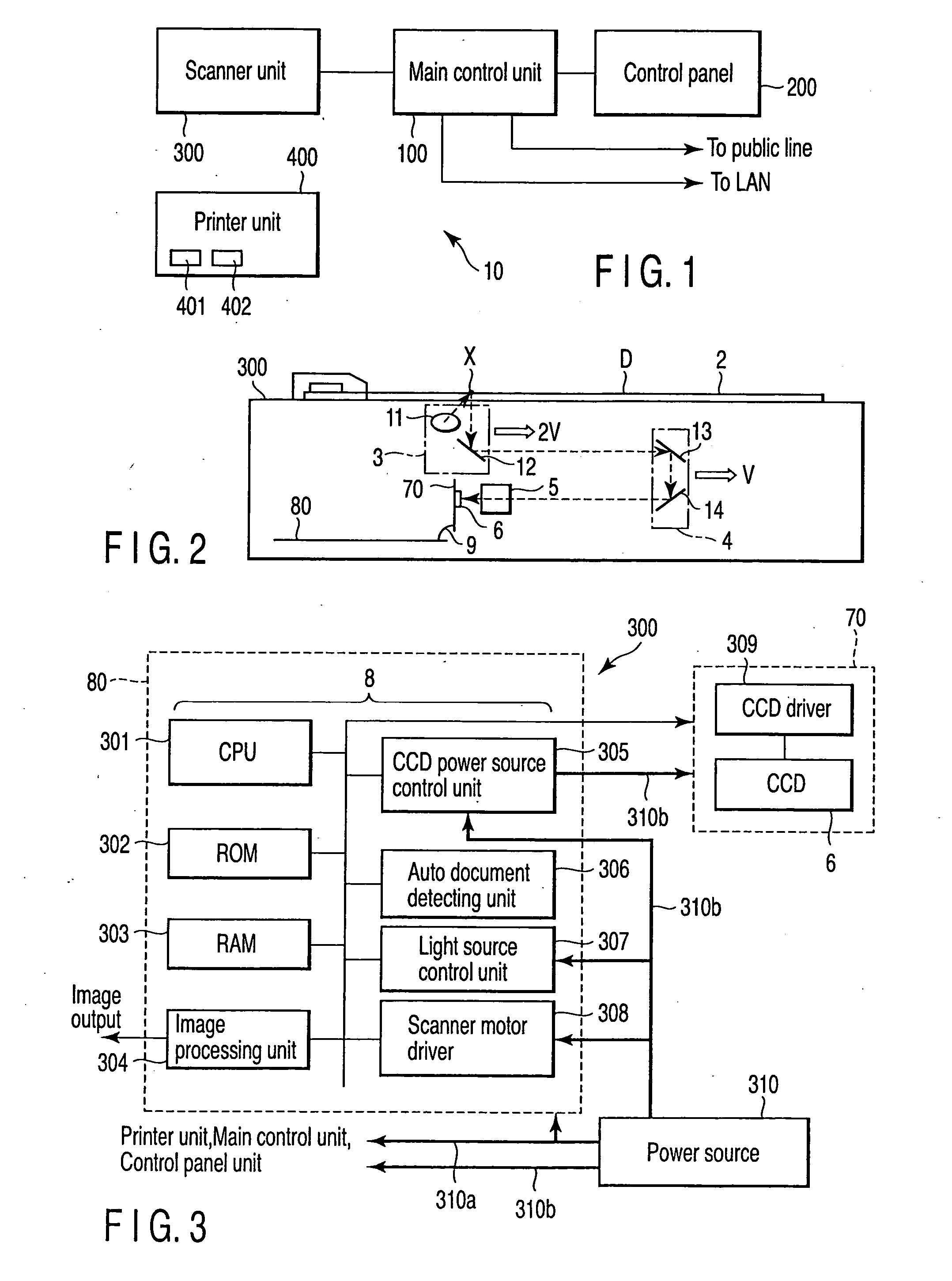
[0017]FIG. 1 is a block diagram schematically illustrating a configuration of an image forming apparatus 10 such as a digital copying machine to which the present invention is applied. The image forming apparatus 10 includes a scanner unit 300 which reads a document image to provide image data corresponding to the document image, a printer unit 400 which forms an image onto a paper sheet on the basis of the image data from the scanner unit 300, a control panel unit 200 which acts as a user interface, and a main control unit 100 which performs overall control of the respective units of the image forming apparatus 10 on the basis of a user instruction inputted via the control panel unit 200.

[0018] The main control unit 100 can facsimile image data on the document read by the scanner unit 300, via a public line such as a telephone line or the like, and the image data r...


PUM


Abstract

An image reading apparatus for reading a document image to provide image data corresponding thereto, including a photoelectric conversion unit which converts a light-received image into an image signal, a photoelectric conversion unit which converts an optical image on a document into an image signal, an image processing unit which processes the image signal outputted from the photoelectric conversion unit, and provides the image data, a power source unit which supplies power to respective units including the photoelectric conversion units and the image processing unit of the image reading apparatus, and a power supply control unit which controls power supply from the power source unit to the photoelectric conversion unit.

Description

BACKGROUND OF THE INVENTION [0001] The present invention is applied to an image reading apparatus such as a document scanner, and an image forming apparatus such as a copying machine, and relates to a method for supplying power to a CCD (Charge Coupled Device) for converting an optical image into an electric signal. [0002] Generally, a scanner that reads a document image has a first carriage having a light source and a first mirror, a second carriage having second and third mirrors, a lens and a CCD, etc. When a document is read by the scanner, the document placed on a document glass plate is illuminated by the light source of the first carriage that moves in the sub-scanning direction. Reflected light from the document is reflected on the first to third mirrors, and is concentrated by the lens and guided to the CCD sensor. At that time, the second carriage moves such that an optical path length of the reflected light from the document to the CCD is constant, in a direction which is...

Claims


Application Information

Patent Timeline
IPC IPC(8): H04N1/00H04N1/04
CPCH04N1/00885H04N2201/0081H04N1/00891
Inventor HASHIZUME, YUSUKEUENO, SUEO
Owner KK TOSHIBA
Why Eureka
Try Eureka